Method of motion compensated temporal noise reduction

a temporal noise and motion compensation technology, applied in the field of video processing, can solve the problems of increasing the computational cost of sorting, severe blurring of images, and few of them used in real products, and achieve the effects of reducing noise, noise reduction, and reducing nois

Inactive Publication Date: 2009-05-19
SAMSUNG ELECTRONICS CO LTD
View PDF4 Cites 17 Cited by
  • Summary
  • Abstract
  • Description
  • Claims
  • Application Information

AI Technical Summary

Benefits of technology

[0009]The present invention addresses the above shortcomings. An object of the invention is to provide a motion compensated temporal noise reduction system. In one embodiment, the present invention provides a method of reducing noise in a sequence of digital video frames is performed by applying motion estimation between a current noisy frame and a previous noise-reduced frame, to generate motion vectors indicating relative motion between the pixels in the current noisy frame and the corresponding pixels in the previous noise-reduced frame; and removing noise from the current noisy frame by computing the weighted average of pixels in the current noise frame and the corresponding pixels in the previous noise-reduced frame based on the motion vectors, to generate a noise-reduced output frame.

Problems solved by technology

Various noise reduction methods have been developed but few of them are used in real products due to the artifacts.
Mean filtering, however, causes severe blurring of images.
However, as the number of input pixels increases, the computational cost of sorting is also increases, making it costly to implement practically.
Such algorithms, however, require expensive hardware and introduce artifacts when edge-detection fails, especially in very noisy images.
Since image details are also high frequency components, such methods also blur the image.
In a non-motion region, pixels are filtered along the temporal axis based on the Maximum Likelihood Estimation, outputting high quality filtered images, but with a drawback of unevenness, caused by switching off temporal filtering in motion regions.
However, such a method requires more frame buffer and frame delay.
Further, such a method cannot perform temporal noise reduction on a moving object.

Method used


Image

  • Method of motion compensated temporal noise reduction
  • Method of motion compensated temporal noise reduction
  • Method of motion compensated temporal noise reduction

Examples


Embodiment Construction

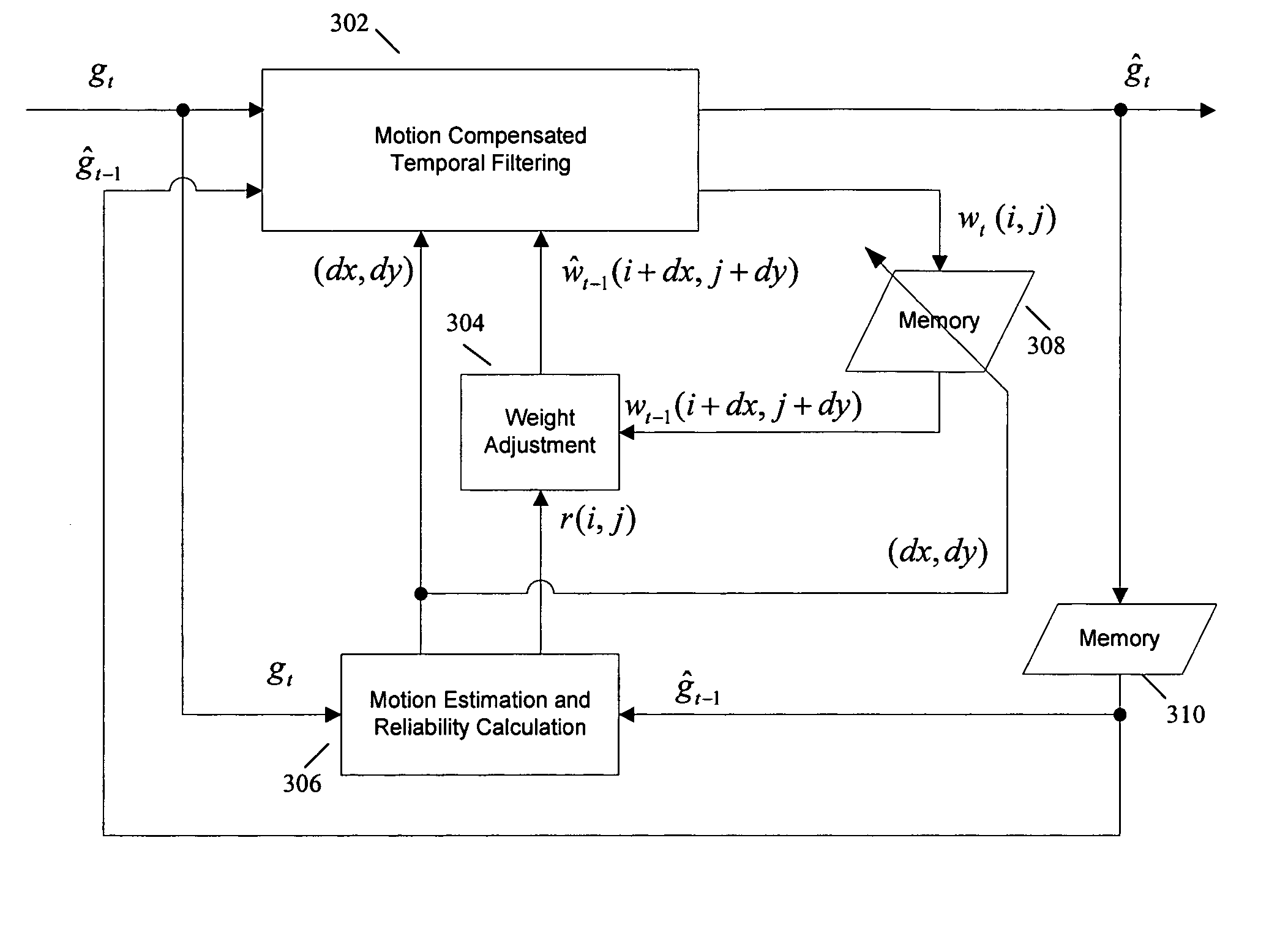
[0020]Preferred embodiments of the present invention are now described in conjunction with the drawings. In one embodiment, the present invention provides a motion compensated temporal noise reduction method and system. In order to systematically describe the temporal noise reduction problem and said embodiment of the present invention, let gt denote the incoming video frame at time instant t and gt(i,j) denote the corresponding pixel value at the coordinates (i,j) where i represents the ordinate and j represents the abscissa. Assume the input video sequence is corrupted by independent, identically distributed additive and stationary zero-mean Gaussian noise with variance σ02, that is, any pixel gt(i,j) can be denoted as:

gt(i,j)=ft(i,j)+nt(i,j),

where ft(i,j) denotes the true pixel value without noise corruption and nt(i,j) is the Gaussian distributed noise component.

[0021]The noise variance σ02 can be pre-detected by a noise estimation unit. Commonly assigned patent application Ser....


PUM


Abstract

A method of reducing noise in a sequence of digital video frames is performed by motion estimation between a current noisy frame and a previous noise-reduced frame, to generate motion vectors indicating relative motion between the pixels in the current noisy frame and the corresponding pixels in the previous noise-reduced frame; and removing noise from the current noisy frame by computing the weighted average of pixels in the current noise frame and the corresponding pixels in the previous noise-reduced frame based on the motion vectors, to generate a noise-reduced output frame.

Description

FIELD OF THE INVENTION[0001]The present invention relates generally to video processing, and more particularly to noise reduction in video sequences.BACKGROUND OF THE INVENTION[0002]In TV systems, the first stage of video enhancement generally is noise reduction in order to obtain noise-free video sequences. Various noise reduction methods have been developed but few of them are used in real products due to the artifacts. Most of the noise reduction methods can be classified into three categories: (1) spatial (2D) noise reduction, (2) temporal noise reduction, and (3) 3D noise reduction. The 3D noise reduction is a combination of 2D and temporal noise reduction.[0003]Spatial noise reduction applies a filter of a small local window on every pixel of the current video frame. Such a filter usually is regarded as a convolution filter based on a kernel. The most common filters are the mean filter, the Gaussian filter, the median filter, the sigma filter, etc. Mean filtering is the simple...

Claims


Application Information

Patent Timeline
Patent Type & Authority Patents(United States)
IPC IPC(8): H04N5/00H04N5/14
CPCH04N5/145H04N5/21H04N19/139H04N19/176H04N19/117H04N19/577
Inventor ZHOU, ZHIKIM, YEONG-TAEGARCE, GONZALO R.
Owner SAMSUNG ELECTRONICS CO LTD
Why Eureka
Try Eureka