
Method and apparatus for optical detection of a phase transition

Active Publication Date: 2008-08-14
STRATEC BIOMEDICAL AG
View PDF12 Cites 11 Cited by
  • Summary
  • Abstract
  • Description
  • Claims
  • Application Information

AI Technical Summary

Benefits of technology

[0011]Against the background of this prior art, the invention allows more accurate detection of the phase boundary while reducing the dead volume.
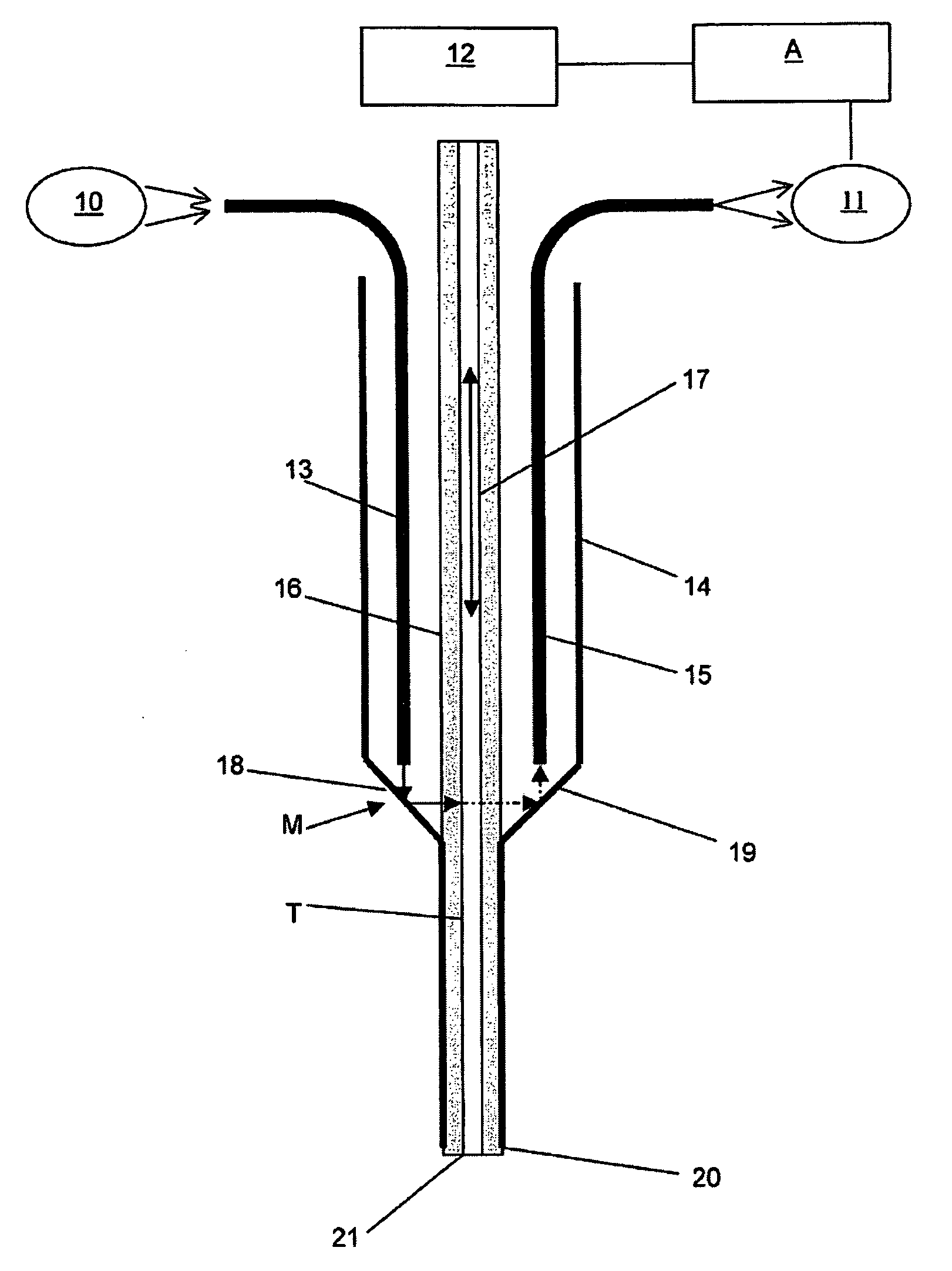
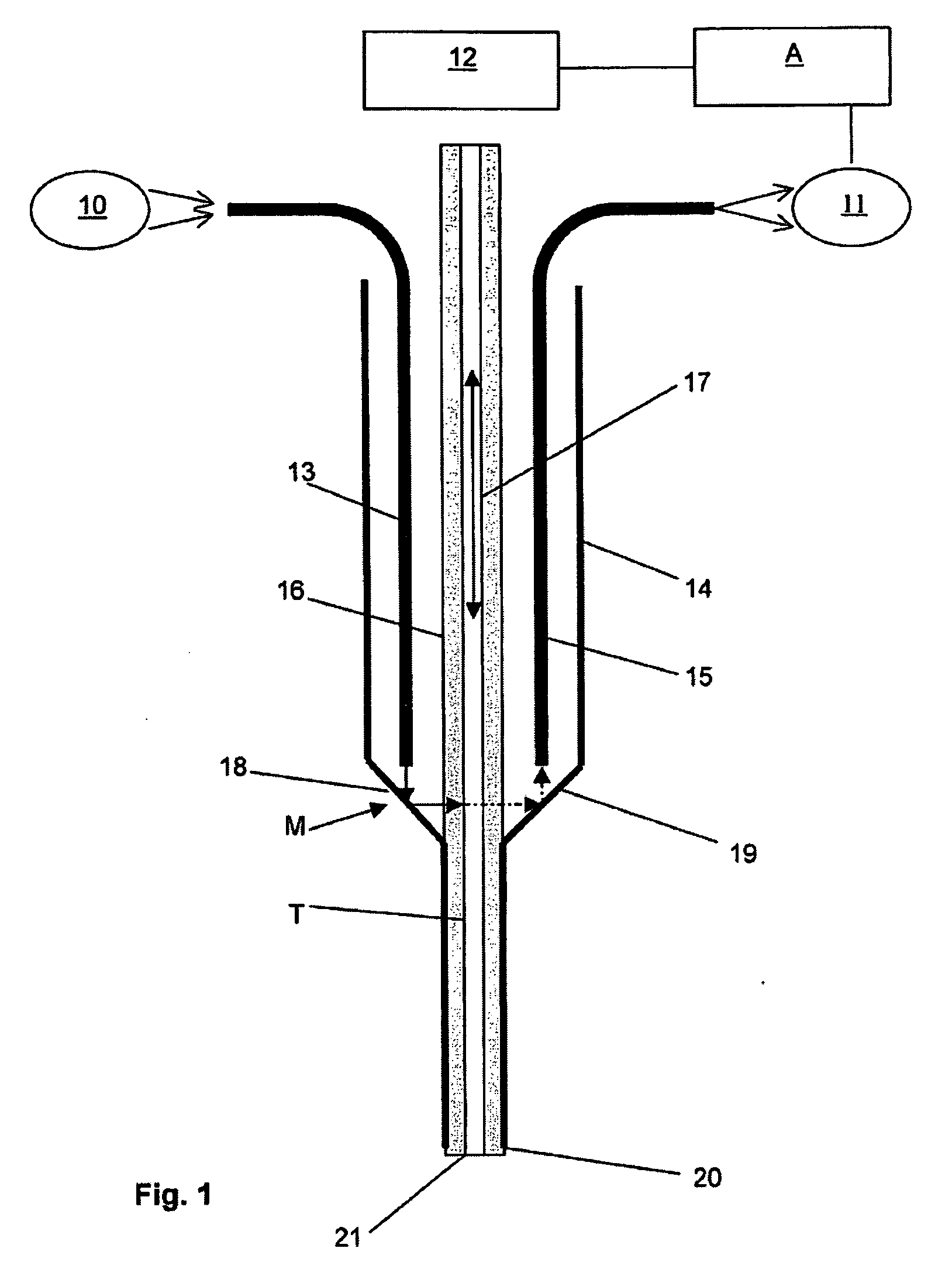
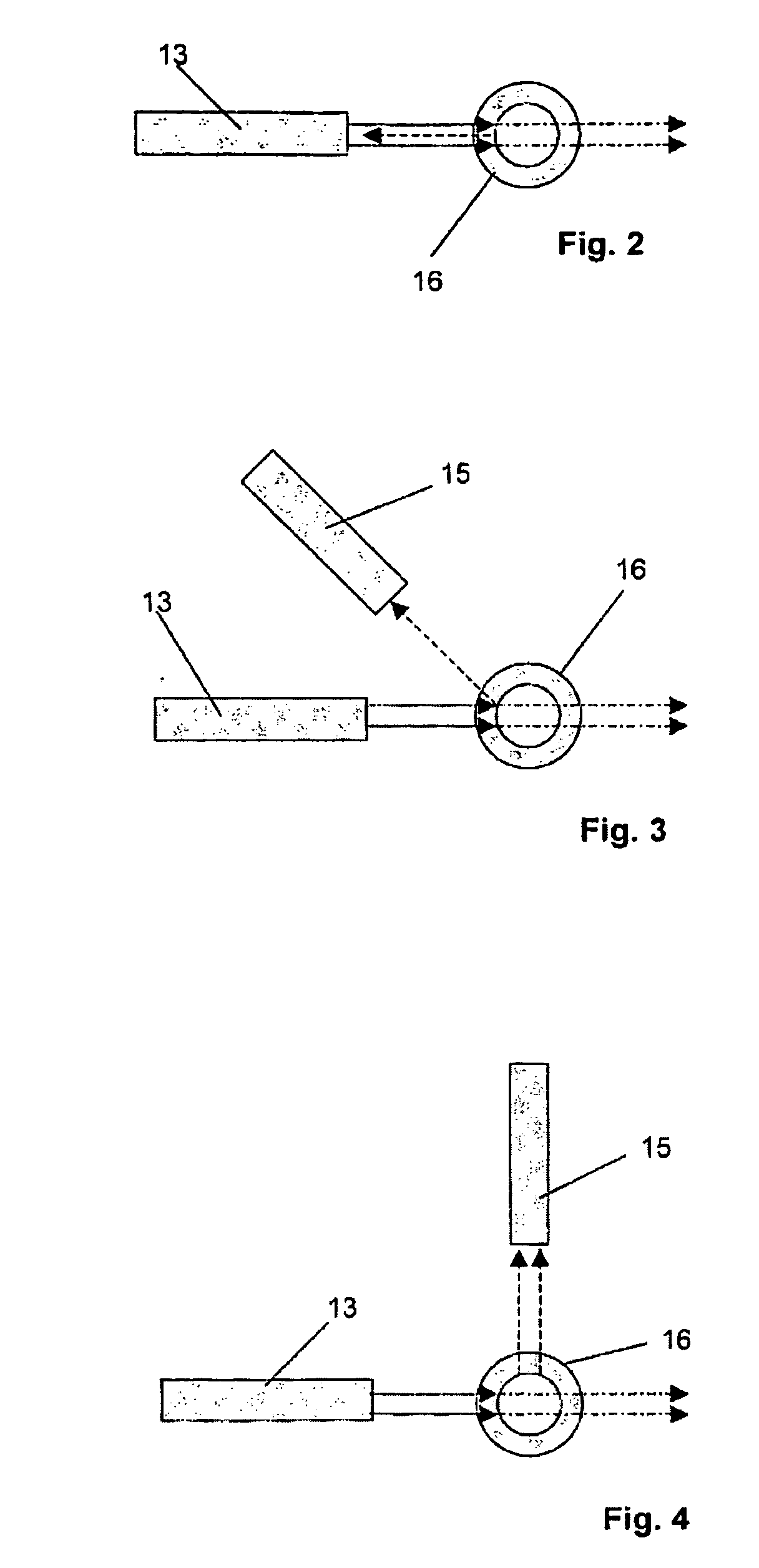
[0013]This device and method comprise the pairing of a conventional intake and / or dispensing device, e.g., a needle made of steel or other materials, optionally nonconducting materials, with a line integrated into it, preferably being transparent for at least one certain radiation, having a fiber optic sensor comprising at least one wave guide. The measurement point of the fiber optic sensor here is placed as close as possible to the intake / delivery opening of the steel needle to minimize the dead volume between the intake / delivery opening and the measurement point. The intake volume is preferably much greater than the dead volume between the measurement point and the intake opening. From the signals detected by the fiber optic sensor, which are in turn influenced by the medium in the line and / or the associated change in the refractive indices, an analyzer unit is able to detect the phase transition between different media on the basis of the received signals that are converted into electric signals, e.g., a phase transition from liquid to air or vice versa. It is likewise possible to detect whether a liquid or gaseous medium, for example, is present in the line, i.e., the static state of media. Due to the fact that the measurement point passes through at least one waveguide that is parallel to the line and a respective deflecting lens as far as possible to the probe and / or to the tip of the pipetting needle, it is possible to recognize much more rapidly than in the state of the art whether the intake and / or dispensing operation has been successful. Furthermore, this compact design can be integrated as needed into the hollow needle of the pipetting device. In particular by means of this design it is possible to test liquids flowing past the measurement point to detect disturbances to thereby at least qualitatively monitor the correct uptake / dispensing of liquids indirectly and thus verify it. If quantitative detection is necessary, the dimensions of the pipetting needle must also be known, and the time between successive phase boundaries can be detected so that the volume flow can be determined.
[0020]Integration of the measurement point into the pipetting tip has positive effects on pipetting quality and efficiency, e.g.,
[0022]shorter contaminated tube distance and therefore short washing times associated with this,
[0023]faster pipetting due to minimized intake paths of the liquids.

Problems solved by technology

Typical detectable errors include, for example:clogged intake opening (clots)poor / no intake (defect in pump, leaking system)intake opening not submerged at the time of intakemix-up of the intake opening in the intake processintake of foamy liquids.

Method used


Image

  • Method and apparatus for optical detection of a phase transition
  • Method and apparatus for optical detection of a phase transition
  • Method and apparatus for optical detection of a phase transition

Examples


Embodiment Construction

[0043]The present invention will now be explained in greater detail by way of example, with reference to the accompanying drawings. However, the exemplary embodiments pertain only to examples, and are not intended to limit the inventive concept to a certain arrangement.

[0044]Before describing the invention in detail, it should be pointed out that it is not limited to the respective components of the device and the respective method steps because these components and methods can vary. The terms used here are intended only to describe special embodiments and are not used restrictively. Furthermore, if the singular or the indefinite article is used in the description or the claims, this may be understood to also refer to a plurality of these elements as long as the overall context does not unambiguously specify the contrary.

[0045]FIG. 1 shows schematically a device for optical detection of at least one phase transition between at least two media and / or a static state of media, which ar...


PUM


Abstract

The device and the method are used for optical detection of at least one phase transition between at least two media, which are taken into a line and / or dispensed from the line by an intake and / or dispensing device. A light-emitting transmitter emits light across and onto the line at a measurement point provided for this purpose. A receiver receives the emitted light, which is influenced by media in the line, to form reception signals. At least one waveguide, which is arranged up to the measurement point on the probe, is provided between the transmitter and / or the receiver and the measurement point (M). Due to the fact that the waveguide is arranged in parallel to the line at least in the area near the probe and at least one deflection lens is provided in the area of the measurement point to deflect the light emitted and / or the light to be detected, a phase boundary or state can be detected, and the dead volume is reduced.

Description

REFERENCE TO RELATED PATENT APPLICATIONS[0001]The present patent application claims the priority of German Patent Application 10 2007 003 040.3 filed on Jan. 20, 2007, the content of which is herein incorporated by reference in its entirety.FIELD OF THE INVENTION[0002]The present invention relates to a device and a method for the optical detection of a phase transition between at least two media or a static state of media.BRIEF DESCRIPTION OF RELATED ART[0003]Such detection of a phase transition and / or a static state is necessary, e.g., in metering operations with liquids, which are often a part of mixing or analytical methods in which accurate doses of liquids are taken from liquid quantities and mixed together, for example. Such operations are routinely performed in chemical, pharmaceutical, medical and human biological procedures, but they may also occur in other technical fields. If the incorrect doses of liquids are not detected, they may lead to results that are objectionable ...

Claims


Application Information

Patent Timeline
IPC IPC(8): G01N21/00
CPCG01F1/74G01F1/704
Inventor BURK, OLIVERTRUMP, MARTIN
Owner STRATEC BIOMEDICAL AG
Learn More