Laser rewriting system

Inactive Publication Date: 2008-08-14
RICOH KK
View PDF29 Cites 76 Cited by
  • Summary
  • Abstract
  • Description
  • Claims
  • Application Information

AI Technical Summary

Benefits of technology

[0009]It is an object of the present invention to at least

Problems solved by technology

However, when operations and the like are performed in various environments, it is troublesome to perform the rewriting operation by using the electronic equipment.
When the detachment and reat

Method used


Image

  • Laser rewriting system
  • Laser rewriting system
  • Laser rewriting system

Examples


first embodiment

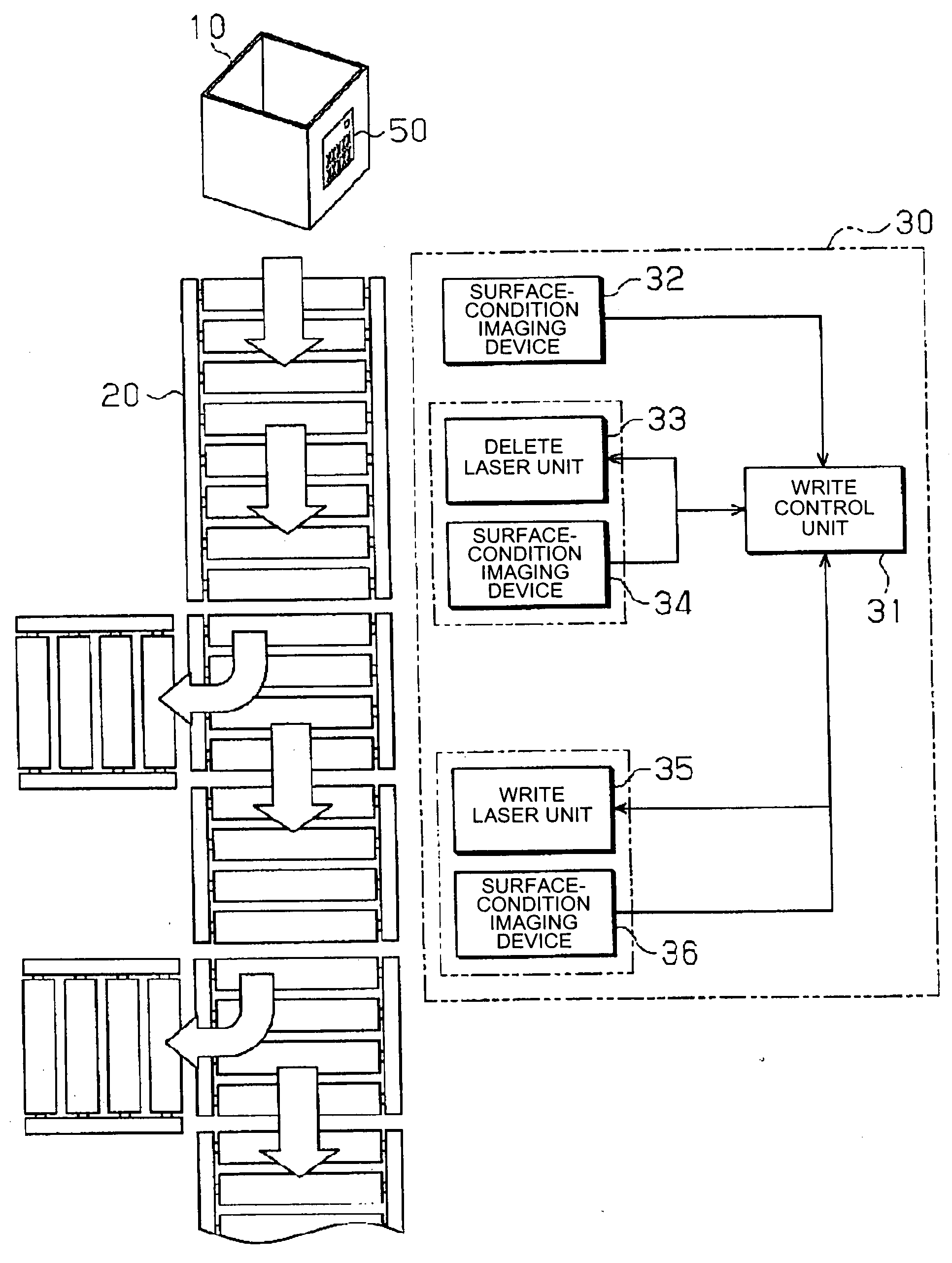
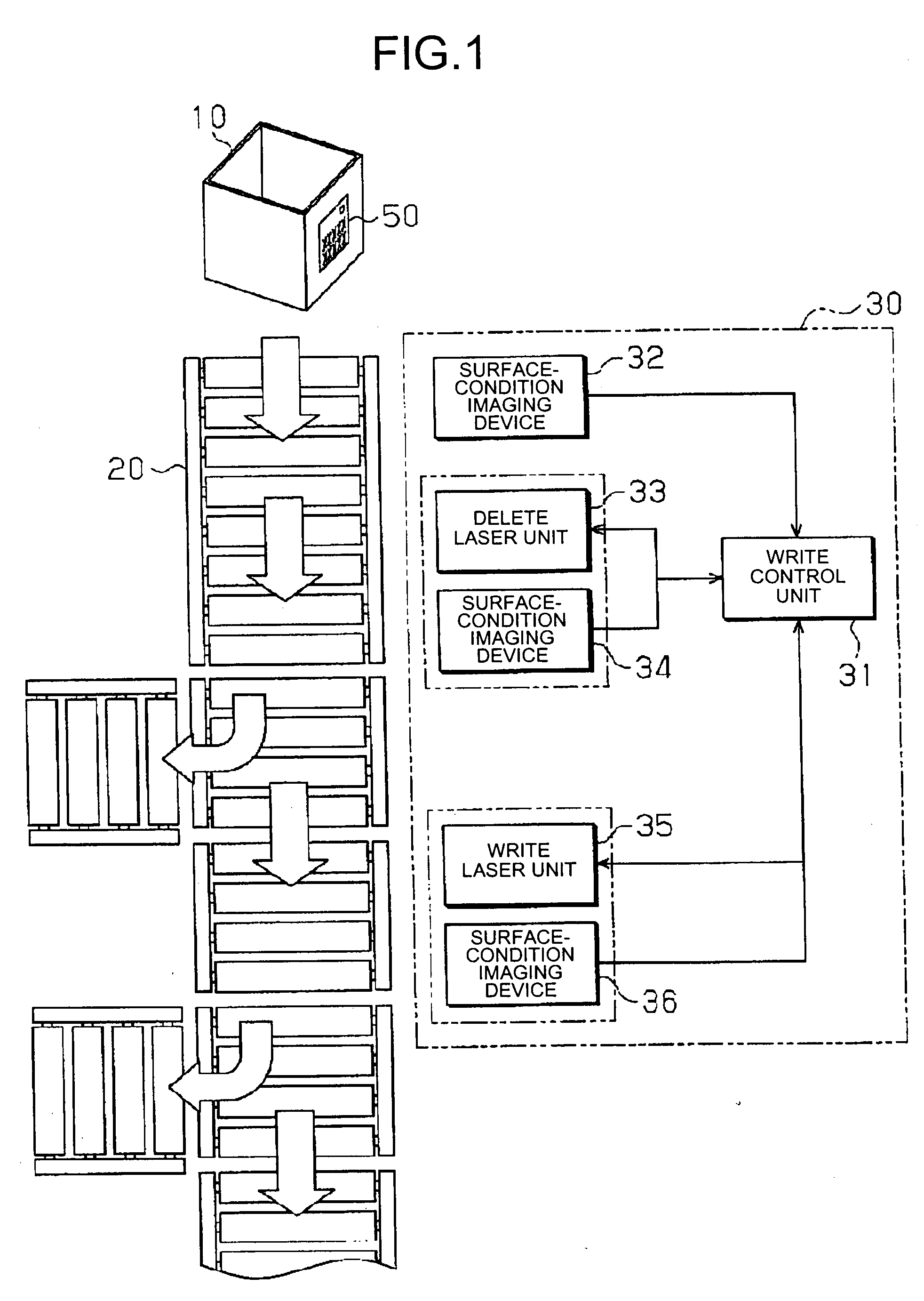
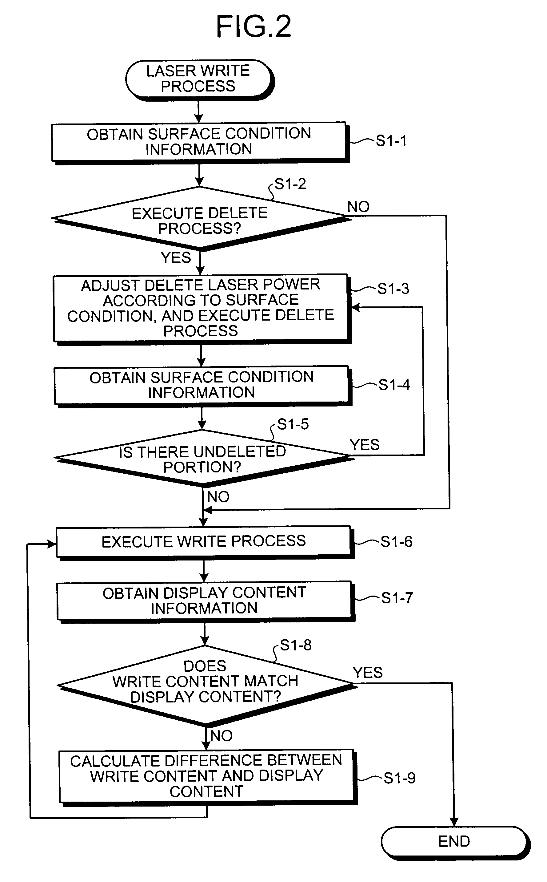
[0015]As shown in FIG. 1, a laser writing apparatus 30 as the laser rewriting system in the embodiment is arranged on the side of a conveying unit 20 as a transport unit on which a container 10 as an object to be managed is placed and carried. The laser writing apparatus 30 includes a write control unit 31, a surface-condition imaging device 32, an erase processing unit including a erase laser unit 33 and a surface-condition imaging device 34, and a write processing unit including a write laser unit 35 and a surface-condition imaging device 36. In the first embodiment, the surface-condition imaging device 32, the erase processing unit, and the write processing unit are arranged in this order from the upstream of the conveying unit 20.

[0016]The write control unit 31 has a central processing unit (CPU), a random access memory (RAM), a read only memory (ROM), and the like (not shown), and functions as a control unit. The write control unit 31 controls the erase laser unit 33 and the wr...

second embodiment

[0048]the present invention is explained with reference to FIG. 3. In the embodiments explained below, like reference numerals refer to like parts as in the first embodiment, and detailed explanations thereof will be omitted. In the second embodiment, the erase process or the write process is different from that of the first embodiment.

[0049]Also in the second embodiment, the laser writing apparatus 30 having the same configuration as that in the first embodiment is used. Also in the second embodiment, the container 10 is carried by the conveying unit 20. When the surface-condition imaging device 32 detects the container 10, the write control unit 31 obtains the surface condition information as at Step S1-1 in the first embodiment (Step S2-1). The write control unit 31 determines whether the erase process is required based on the surface condition information (Step S2-2). When it is determined that the erase process is required (YES at Step S2-2), the write control unit 31 executes ...

third embodiment

[0057]the present invention is explained with reference to FIG. 4. In the third embodiment, the erase process or the write process is different from that in the first and second embodiments.

[0058]Also in the third embodiment, the laser writing apparatus 30 having the same configuration as that in the first embodiment is used. Also in the second embodiment, the container 10 is carried by the conveying unit 20. When the surface-condition imaging device 32 detects the container 10, the write control unit 31 obtains the surface condition information as at Step S1-1 in the first embodiment (Step S3-1). The write control unit 31 determines whether the erase process is required based on the surface condition information (Step S3-2). When it is determined that the erase process is required (YES at Step S3-2), the write control unit 31 executes the erase process as at Step S1-3 (Step S3-3).

[0059]After the erase process is performed by the erase laser unit 33, the write control unit 31 obtain...


PUM


Abstract

A surface-condition-information obtaining unit obtains information on a surface condition of a rewritable display medium on which information is reversely displayed visually. A write-laser output unit outputs a write laser to irradiate the rewritable display medium with the write laser, to perform a drawing on the rewritable display medium. A control unit performs a write process for displaying an image on the rewritable display medium by adjusting a laser output condition based on the information obtained by the surface-condition-information obtaining unit and controlling the write-laser output unit based on an adjustment of the laser output condition.

Description

CROSS-REFERENCE TO RELATED APPLICATIONS[0001]The present application claims priority to and incorporates by reference the entire contents of Japanese priority document 2007-031232 filed in Japan on Feb. 9, 2007.BACKGROUND OF THE INVENTION[0002]1. Field of the Invention[0003]The present invention relates to a laser rewriting system that performs writing with respect to a rewritable recording medium.[0004]2. Description of the Related Art[0005]Recently, information recording media having various pieces of electronic information stored therein are used. A printing technique of visualizing electronic information stored in such information recording media has been disclosed (see, for example, Japanese Patent Application Laid-open No. 2004-258699 (page 1 and FIG. 1)). According to the technique described in Japanese Patent Application Laid-open No. 2004-258699, the information recording medium includes a rewrite area in which change information including at least one image can be rewritte...

Claims


Application Information

Patent Timeline
IPC IPC(8): G11B7/00
CPCB41J2/32B41J2/4753B41J2/355
Inventor NAKATA, YOSHIKONAKAJIMA, TSUTOMUOCHIAI, NORIYUKISAHASHI, YUKIKOHOTTA, YOSHIHIKOKAWAHARA, SHINYAUENISHI, HIROSHIISHIMI, TOMOMI
Owner RICOH KK
Why Eureka
Try Eureka