In-Vehicle Apparatus For Recognizing Running Environment Of Vehicle

Active Publication Date: 2008-08-14
HITACHI ASTEMO LTD
View PDF9 Cites 76 Cited by
  • Summary
  • Abstract
  • Description
  • Claims
  • Application Information

AI Technical Summary

Benefits of technology

[0008]The present invention is capable of providing the in-vehic

Problems solved by technology

When detecting a target outside a vehicle by processing the images photographed by an imaging device, in some cases, the detection process cannot be appropriately performed due to influences exerted by such a cause as sunlight or other vehicle's headlight.
As a result, t

Method used


Image

  • In-Vehicle Apparatus For Recognizing Running Environment Of Vehicle
  • In-Vehicle Apparatus For Recognizing Running Environment Of Vehicle
  • In-Vehicle Apparatus For Recognizing Running Environment Of Vehicle

Examples


embodiment 1

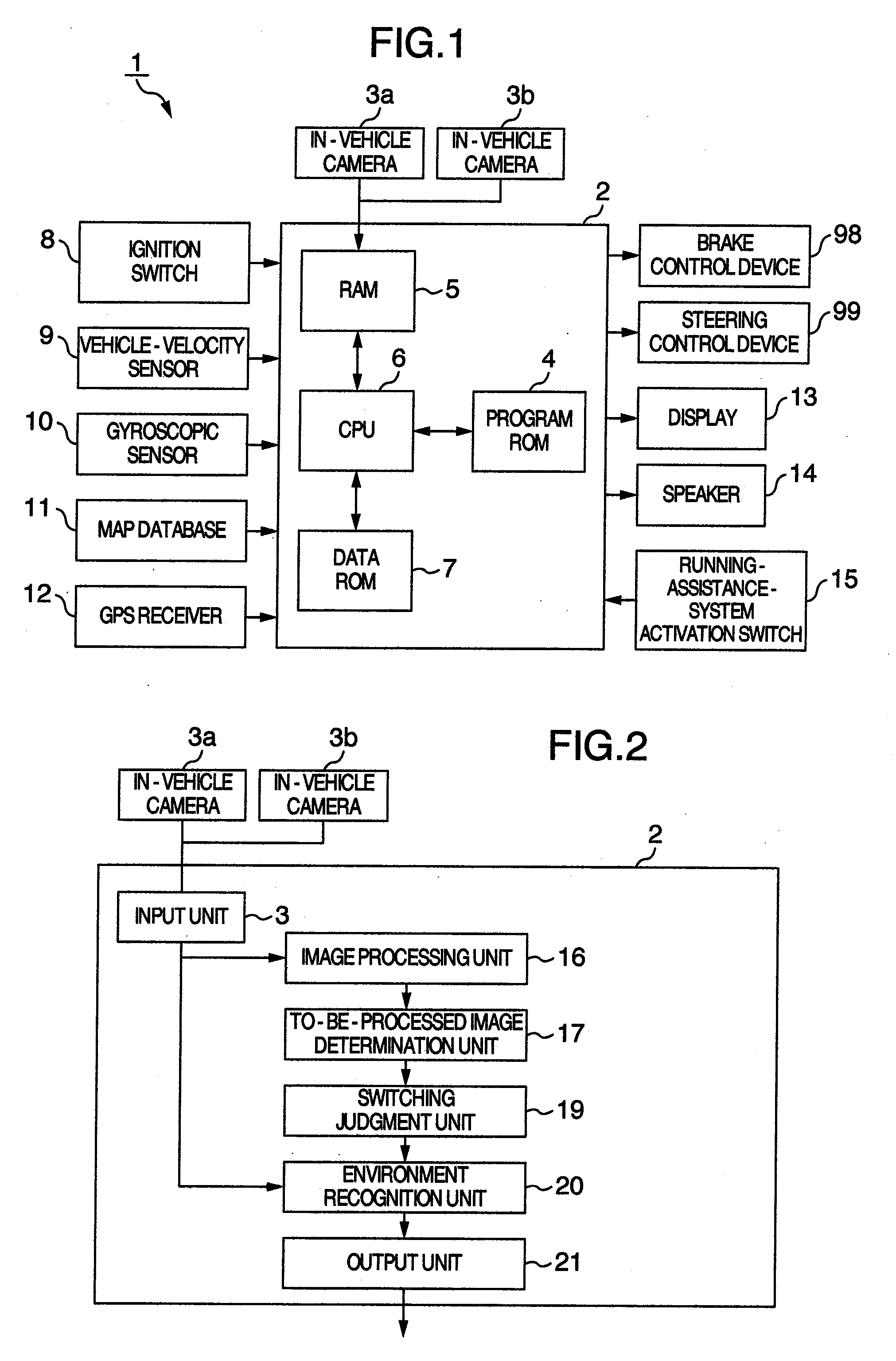
[0042]FIG. 1 illustrates a block configuration diagram of an in-vehicle system 1 which embodies a first embodiment.

[0043]The in-vehicle system 1 illustrated in FIG. 1 is the following system: The system, which is mounted on a vehicle, detects the position of the vehicle, guides its running route, and prevents the vehicle from deviating from the lane. The in-vehicle system 1 includes, as imaging devices, an in-vehicle camera 3a for photographing an image positioned forward of the vehicle, and another in-vehicle camera 3b for photographing an image positioned backward of the vehicle. The in-vehicle system 1 further includes a display 13 set up inside the vehicle compartment for displaying respective types of images and respective types of information, a speaker 14 for generating a warning voice when there is a danger of the vehicle's deviating from the running lane, an activation switch 15 for allowing the driver to operate the activation of a running assistance system, and a running-...

embodiment 2

[0086]Referring to the drawings, the explanation will be given below concerning a second embodiment.

[0087]FIG. 14 illustrates a functional block diagram of the running-environment recognition apparatus 2 as the second embodiment. Incidentally, with respect to the configuration of the in-vehicle system 1 of the present embodiment, the same reference numerals will be affixed to basically the same configuration components in the drawings, and the overlapped explanation thereof will be omitted.

[0088]The present embodiment is applied to the in-vehicle system 1 as illustrated in FIG. 1. As illustrated in FIG. 14, the running-environment recognition apparatus 2 includes the image processing unit 16, the to-be-processed image determination unit 17, the switching judgment unit 19, the environment recognition unit 20, a reliability judgment unit 18, a function-switching judgment unit 22, and the output unit 21.

[0089]The reliability judgment unit 18 possesses a function of contrasting and comp...

embodiment 3

[0115]Referring to the drawings, the explanation will be given below concerning a third embodiment.

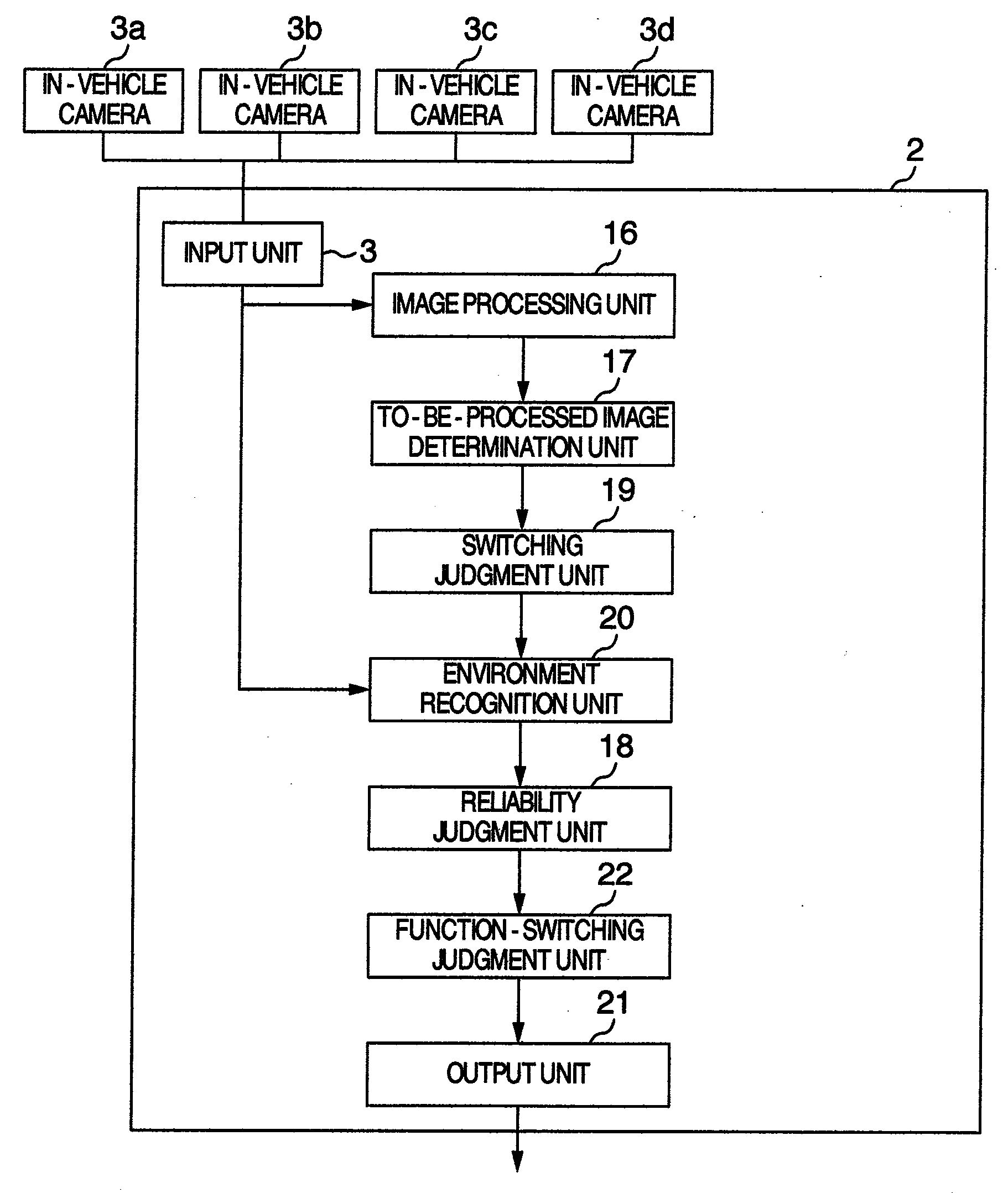
[0116]FIG. 23 illustrates a functional block diagram of a running-environment recognition apparatus 31 which embodies the third embodiment. Incidentally, with respect to the configuration of the in-vehicle system 31 of the present embodiment, the same reference numerals will be affixed to basically the same configuration components in the drawings, and the overlapped explanation thereof will be omitted.

[0117]The present embodiment is applied to the in-vehicle system 31 as illustrated in FIG. 23. The in-vehicle system 31 implements the following function: Namely, the in-vehicle camera 3a, the in-vehicle camera 3b, an in-vehicle camera 3c, and an in-vehicle camera 3d included in this in-vehicle system 31 recognize an environment in the surroundings of the vehicle. Then, if there is a danger of the vehicle's colliding with a vehicle or an obstructing object on the periphery of the vehicle...


PUM


Abstract

An in-vehicle running-environment recognition apparatus including an input unit for inputting an image signal from in-vehicle imaging devices for photographing external environment of a vehicle, an image processing unit for detecting a first image area by processing the image signal, the first image area having a factor which prevents recognition of the external environment, an image determination unit for determining a second image area based on at least any one of size of the first image area, position thereof, and set-up positions of the in-vehicle imaging devices having the first image area, an environment recognition processing being performed in the second image area, the first image area being detected by the image processing unit, and an environment recognition unit for recognizing the external environment of the vehicle based on the second image area.

Description

BACKGROUND OF THE INVENTION[0001]The present invention relates to technologies for processing images photographed by such devices as an in-vehicle camera.[0002]In recent years, the development has been proceeding concerning the following technology: The external environment of a vehicle is recognized based on the images photographed by an imaging device mounted on the vehicle. Moreover, the automatic driving or driving assistance is performed based on the recognition result.[0003]When detecting a target outside a vehicle by processing the images photographed by an imaging device, in some cases, the detection process cannot be appropriately performed due to influences exerted by such a cause as sunlight or other vehicle's headlight. As a solution for this problem, there has been known the following technology (refer to, e.g., JP-A-05-205196): One image input device is provided at each of the front and rear of the vehicle. Then, if contrast of an image photographed by the front-positi...

Claims


Application Information

Patent Timeline
IPC IPC(8): G06K9/00
CPCG08G1/16G06K9/00791G06K9/00798G08G1/167G08G1/166G06V20/588G06V20/56
Inventor HIGUCHI, MIRAIOTSUKA, YUJISHIMA, TAKESHIMACHII, KIMIYOSHIMURAMATSU, SHOJIIRIE, KOTAMONJI, TATSUHIKO
Owner HITACHI ASTEMO LTD
Why Eureka
Try Eureka