High intensity focused ultrasound transducer with acoustic lens

Active Publication Date: 2008-08-14
ST JUDE MEDICAL ATRIAL FIBRILLATION DIV
View PDF33 Cites 81 Cited by
  • Summary
  • Abstract
  • Description
  • Claims
  • Application Information

AI Technical Summary

Benefits of technology

[0031]An advantage of the present invention is that it utilizes lower cost acoustic components having one or more surfaces that are at least manufactured as flat.
[0032]The foregoing and other

Problems solved by technology

One challenge in the design of reliable HIFU transducers is placing the therapeutic heat at the desired location without allowing acoustic heating or secondary, loss-related heating to damage the transducer or non-targeted tis

Method used


Image

  • High intensity focused ultrasound transducer with acoustic lens
  • High intensity focused ultrasound transducer with acoustic lens
  • High intensity focused ultrasound transducer with acoustic lens

Examples


Embodiment Construction

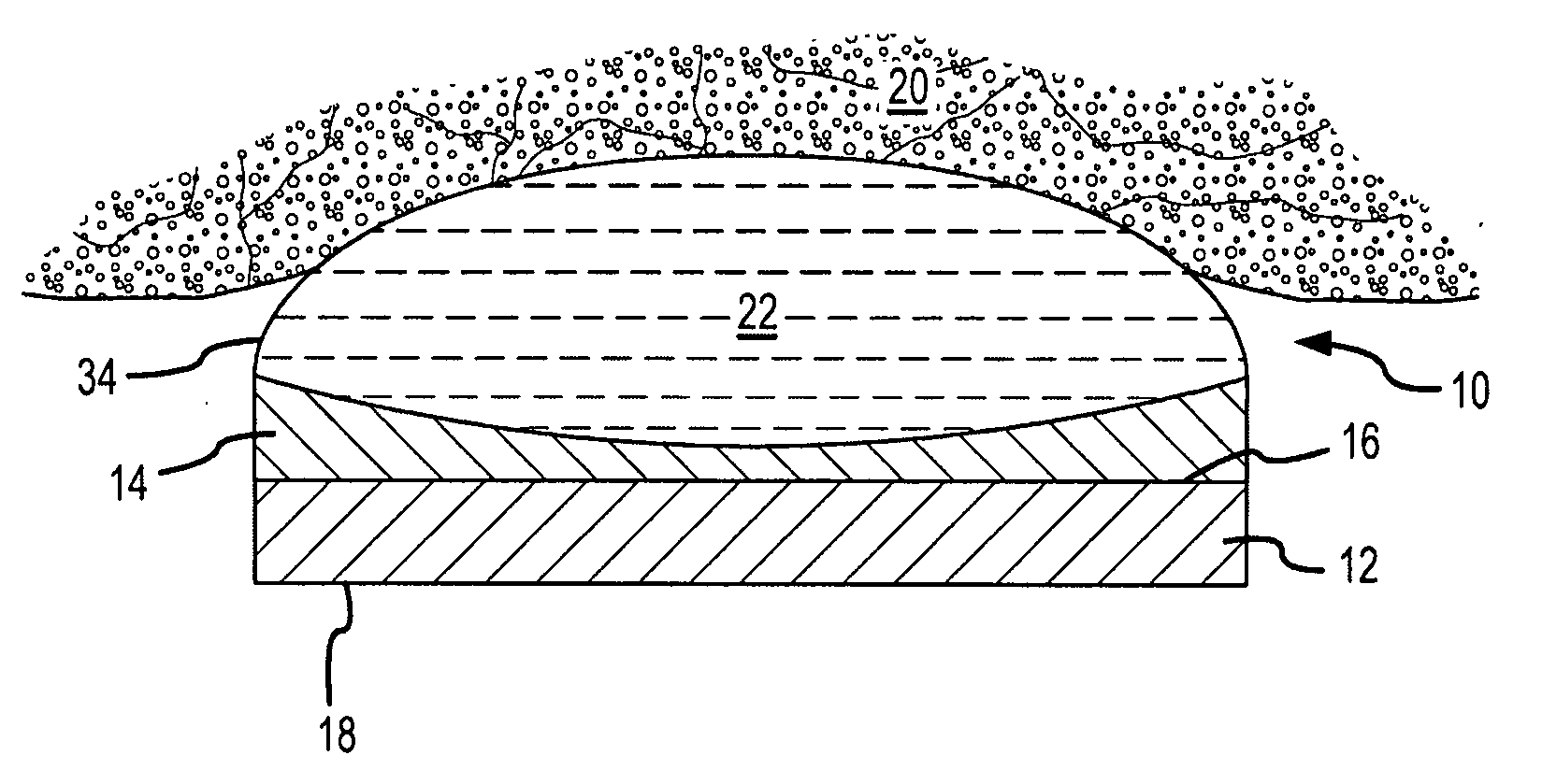
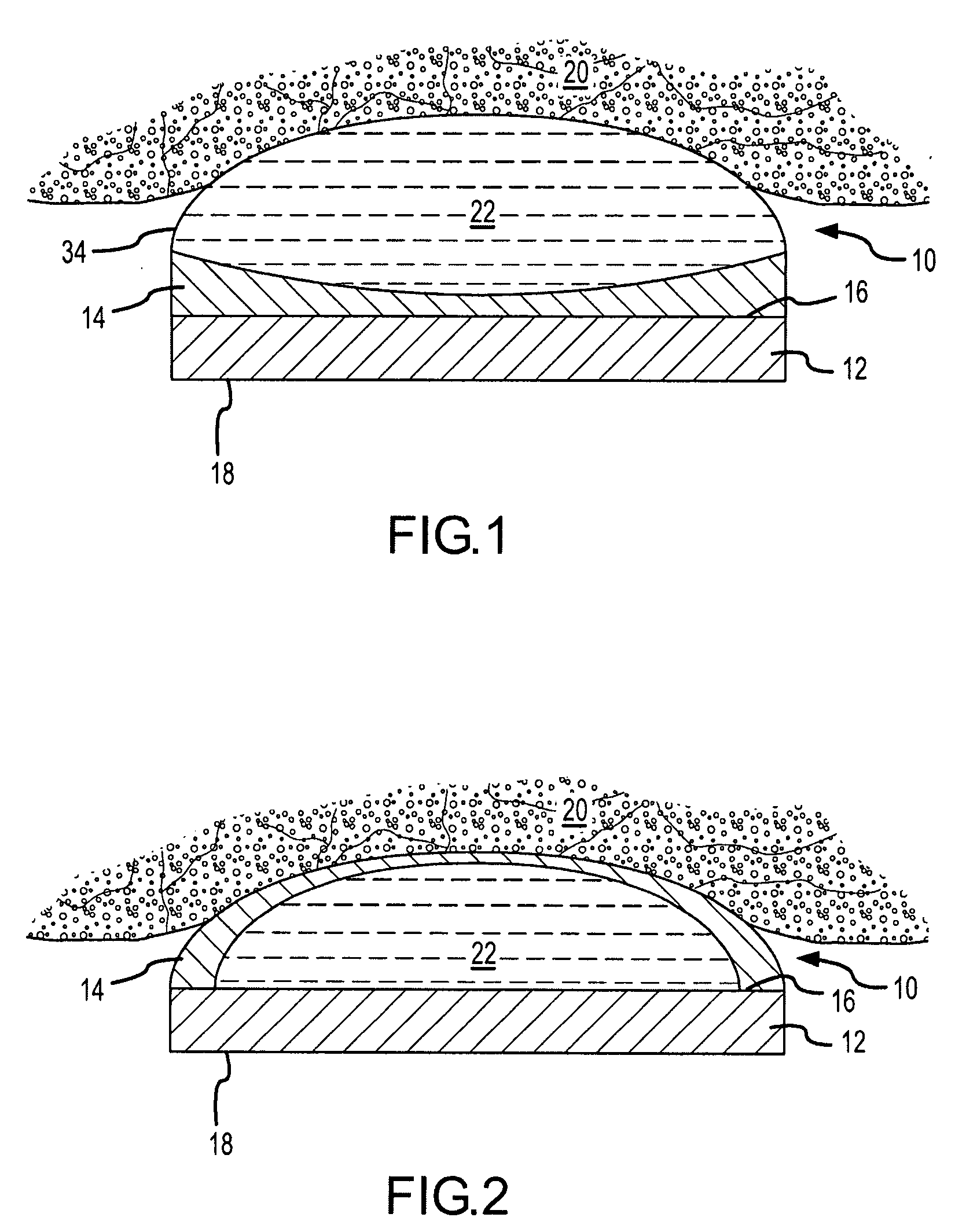
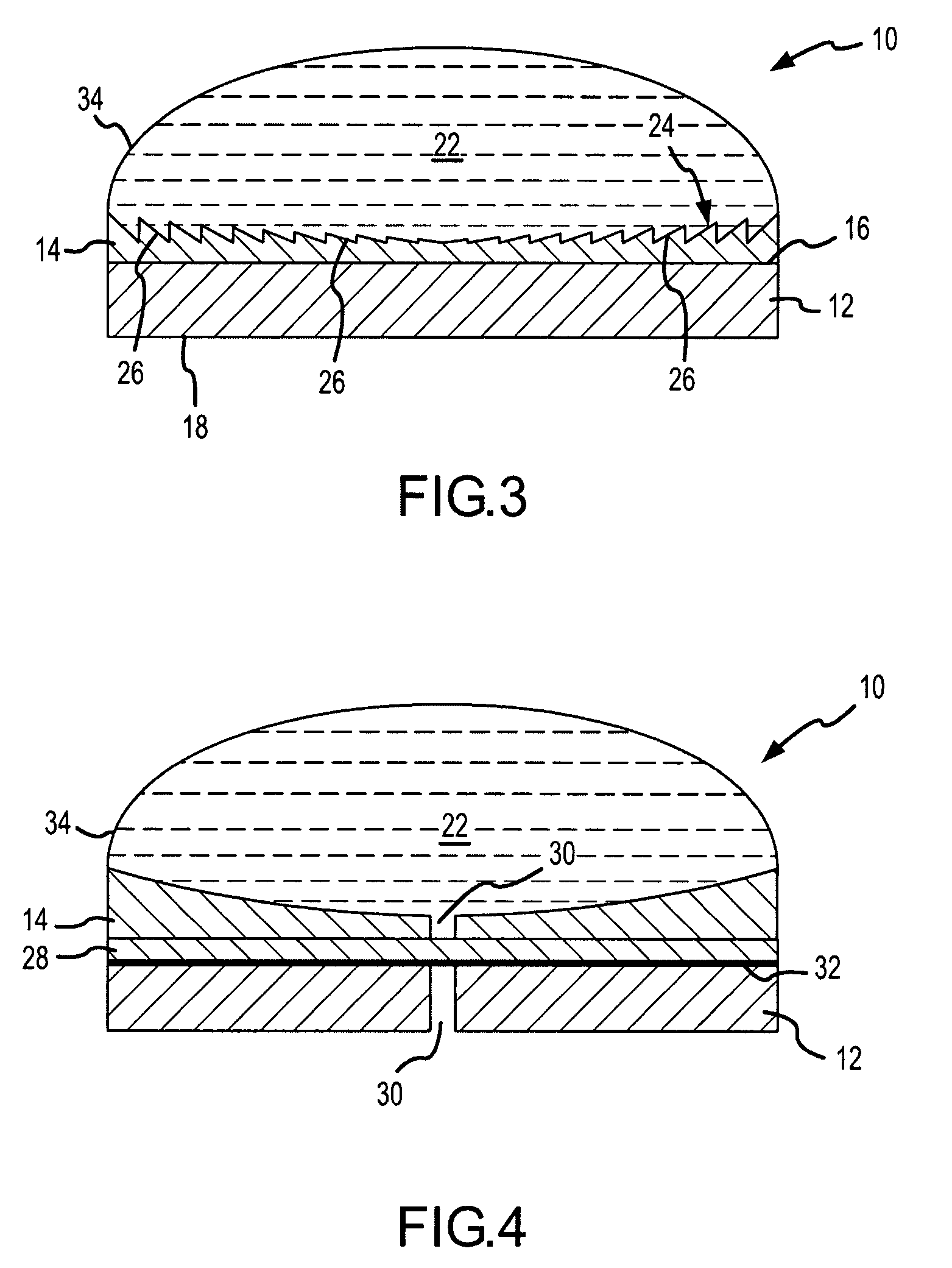
[0045]The present invention provides a high intensity focused ultrasound (HIFU)-capable transducer incorporating one or more acoustic lenses. The invention will be described first with reference to the general features of such a transducer, and then several embodiments will be described with greater particularity. Though the invention will be described in connection with HIFU applications, it is contemplated that the invention may also be practiced in non-HIFU applications, for example ultrasonic imaging applications.

[0046]FIG. 1 depicts an elevational cross-section of an exemplary HIFU transducer 10. HIFU transducer 10 generally includes a first ultrasonic emitter 12 that generates ultrasonic energy, at least one polymeric ultrasonic lens 14, and at least one stress mitigation feature that is configured to mitigate thermal expansion mismatch stresses arising between first ultrasonic emitter 12 and ultrasonic lens 14 during operation of HIFU transducer 10. HIFU transducer 10 typical...


PUM


Abstract

A high intensity focused ultrasound transducer includes an ultrasonic emitter having a surface that emits ultrasonic energy along a beam path, at least one low attenuation polymeric ultrasonic lens acoustically coupled to the surface in the beam path of the ultrasonic energy, such that the lens can direct the ultrasonic energy in at least one direction, and at least one stress mitigation feature, such as a kerf, a heat sink, or an acoustic matching layer, to mitigate thermal expansion mismatch stresses within the transducer. For manufacturing simplicity, the first surface is typically either flat or monotonically curvilinear. The lens may take a variety of shapes, including Fresnel features, and may focus, collimate, or defocus the ultrasonic energy. Any orientation and positioning of the at least one ultrasonic lens relative to the first ultrasonic emitter is contemplated. Manufacture is further simplified by molding, casting, or thermoforming the lens.

Description

CROSS-REFERENCE TO RELATED APPLICATIONS[0001]This application is related to U.S. application Ser. No. 11 / 646,526, filed 28 Dec. 2006 and entitled “Apparatus and Method for Ablating Tissue” (Attorney Docket No. 0E-040801US / 82410-0148), U.S. application Ser. No. 11 / 646,528, filed 28 Dec. 2006, U.S. application Ser. No. 11 / 642,923, filed 21 Dec. 2006, U.S. application Ser. No. 11 / 642,821, filed 21 Dec. 2006, U.S. application Ser. No. 11 / 647,295, filed 29 Dec. 2006, U.S. application Ser. No. 11 / 646,524, filed 28 Dec. 2006, and U.S. application Ser. No. 11 / 703,783, filed concurrently herewith and entitled “Device and Method for High Intensity Focused Ultrasound Ablation with Acoustic Lens” (Attorney Docket No. 0E-042300US / 82410-0177). The foregoing applications are hereby incorporated by reference in their entirety as though fully set forth herein.BACKGROUND OF THE INVENTION[0002]a. Field of the Invention[0003]The instant invention relates to ultrasound medical procedures. In particular,...

Claims


Application Information

Patent Timeline
IPC IPC(8): A61B8/00
CPCA61N7/02A61B17/2251A61B8/4272
Inventor SLIWA, JOHN W.GOETZ, PETERMA, ZHENYITENG, JENNIFERMORSE, STEPHENCALLAGHAN, FRANKCICIARELLI, TIMOTHY E.
Owner ST JUDE MEDICAL ATRIAL FIBRILLATION DIV
Why Eureka
Try Eureka