Large Resisting Distortion and Modularized Comb-Type Bridge Expansion Joint

a comb-type bridge and resistive distortion technology, applied in bridges, bridge construction, bridges, etc., can solve the problems of easy breakage of comb teeth, damage to the expansion joint, and inability to meet the need for such a shift, so as to and reduce the damage of the expansion join

Active Publication Date: 2008-08-21
XU BIN
View PDF2 Cites 10 Cited by
  • Summary
  • Abstract
  • Description
  • Claims
  • Application Information

AI Technical Summary

Benefits of technology

[0013]Compared with the prior art, in this invention, when the girders have transverse shift under the effect of the wind or other external forces, the movable comb plate and its comb teeth will rotate correspondingly and the comb teeth of the fixed comb plate will also rotate correspondingly, and under the effect of the resilient damp material, the forces from flexibility distortion can efficaciously be weaken and the wallop and vibration of vehicles can also be dissolved. Therefore, the wearing out and the damage of the expansion joint will both be mitigated, and the broken of the comb teeth can be avoided. At the sam

Problems solved by technology

Then either the traditional modulus-type or the comb-type bridge expansion joint cannot meet the need for such shift.
And to the comb-type bridge expansion joint, since

Method used


Image

  • Large Resisting Distortion and Modularized Comb-Type Bridge Expansion Joint
  • Large Resisting Distortion and Modularized Comb-Type Bridge Expansion Joint
  • Large Resisting Distortion and Modularized Comb-Type Bridge Expansion Joint

Examples


Embodiment Construction

[0034]To enable a further understanding of the innovative and technological content of the invention herein, refer to the detailed description of the invention and the accompanying drawings below:

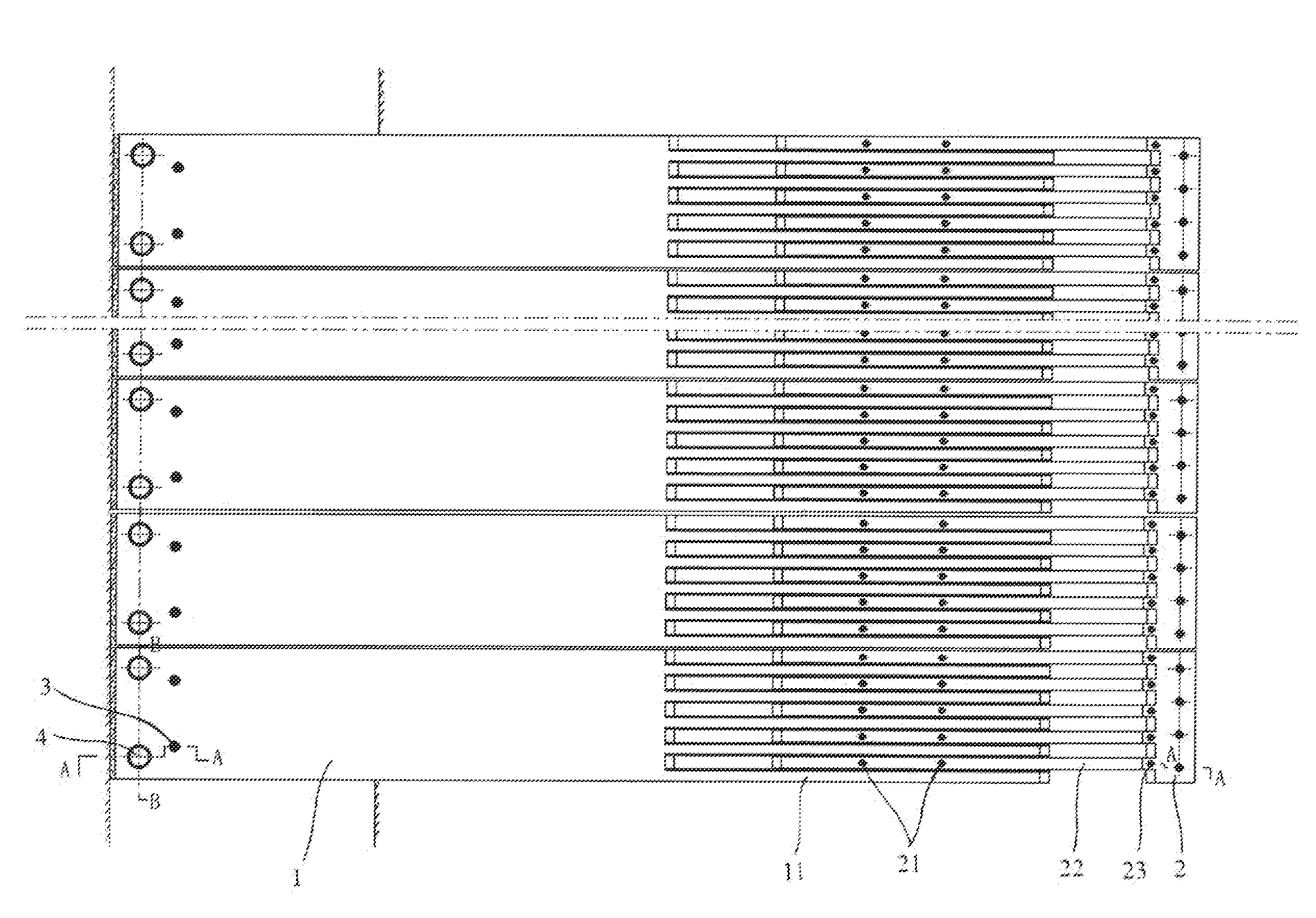
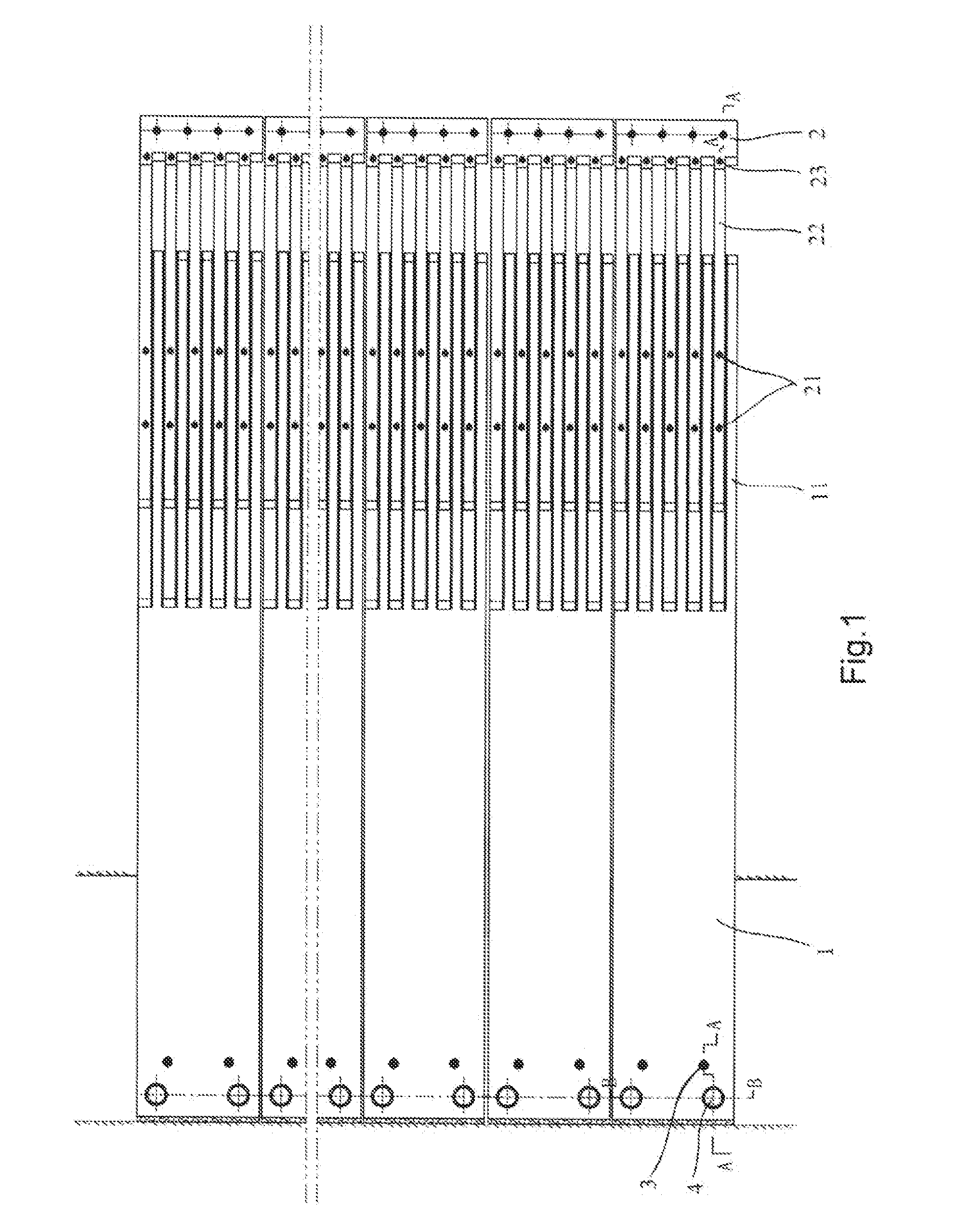
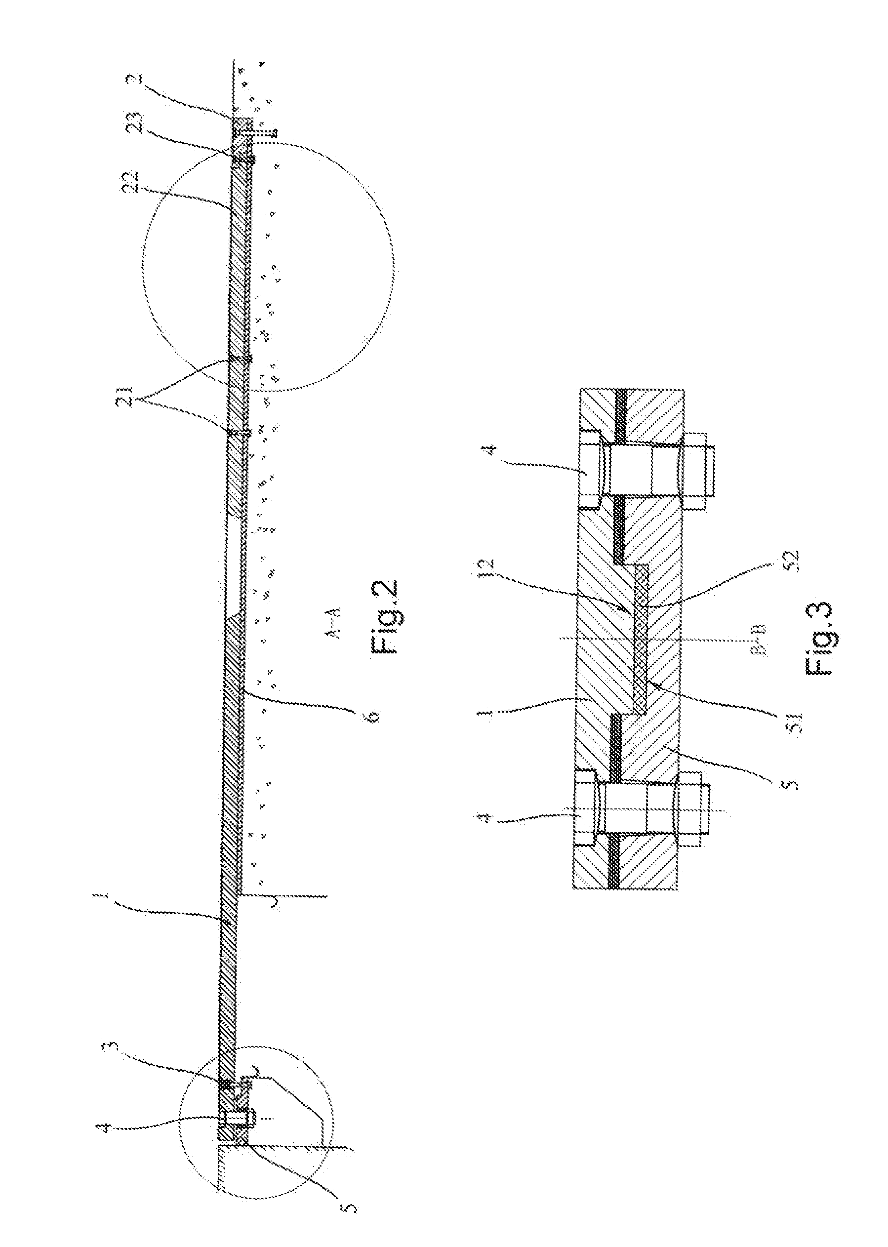
[0035]FIGS. 1˜9 show the first embodiment of the present invention applied to steel girder. In this embodiment, the large resisting distortion and modularized comb-type bridge expansion joint comprises several modules which locate in parallel in the direction of a bridge's width, and each module includes a fixed comb plate 2 and a movable comb plate 1 which are respectively disposed on girders located at the two sides of the bridge expansion joint, the movable comb plate 1 crosses over the bridge expansion joint, both of the fixed comb plate 2 and the movable comb plate 1 have a plurality of comb teeth 22, 11 at their opposite ends, and the comb teeth 11 of the movable comb plate 1 interdigitate with the comb teeth 22 of the fixed comb plate 2, as shown in FIG. 1 and FIG. 2.

[0036]The root o...


PUM


Abstract

A large resisting distortion and modularized comb-type bridge expansion joint, comprises at least two modules located parallel in the direction of a bridge's width, and each module includes a fixed comb plate (2) and a movable comb plate (1), which are respectively disposed on girders located at the two sides of the bridge expansion joint, said movable comb plate (1) crosses over the bridge expansion joint, both of said fixed comb plate (2) and said movable comb plate (1) have a plurality of comb teeth (22), (11) at their opposite ends, and the comb teeth (11) of said movable comb plate (1) interdigitate with the comb teeth (22) of said fixed comb plate (2) characterized in that the root of said movable comb plate (1) rotatably joints with a seat (5) fixed on the girders, and the comb teeth (22) of said fixed comb plate (2) rotatably joints with the root of said fixed comb plate (2), while, the middle of the comb teeth (22) of said fixed comb plate (2) is movably set on an underlay (6) fixed on the girders and can be shifted transversely relative to the underlay (6). In this invention, when the girders have transverse shift under the effect of the wind or other external forces, the movable comb plate and its comb teeth will rotate correspondingly and the comb teeth of the fixed comb plate will also rotate correspondingly, then the broken of the comb teeth will be avoided.

Description

FIELD OF THE INVENTION[0001]The present invention relates to bridge expansion joint, in particular, to a large resistive distortion and modularized comb-type bridge expansion joint.BACK GROUND OF THE INVENTION[0002]Among recent bridge expansion joints, a relatively good technique is the comb-type expansion joint, which comprises a fixed comb plate and a movable comb plate cooperating with each other, and it is especially applied in the large bridge expansion joint whose expansion amount is more than 160 mm. For example, the Chinese patent No. ZL00264872.0 titled “Assemble Type Comb-type Bridge Expansion Joint” disclosed that invented by Bin Xu, the bridge expanding movement is provided by the movable comb plate which crosses on the bridge expansion, no lengthways transition space is existed between the fixed comb plate and the movable comb plate, and the device is connects the bridge surface and road surface as a whole, thereby, the ability of resisting vibration is very good, the v...

Claims


Application Information

Patent Timeline
IPC IPC(8): E01D19/06
CPCE01D19/06
Inventor XU, BIN
Owner XU BIN
Why Eureka
Try Eureka