Slider for slide fastener

Active Publication Date: 2008-08-21
YKK CORP
View PDF4 Cites 3 Cited by
  • Summary
  • Abstract
  • Description
  • Claims
  • Application Information

AI Technical Summary

Benefits of technology

[0019]Although the pull tab attaching lever is deformed due to distortion relative to the body by an operation of pulling the pull tab attached to the pull tab attaching lever, the upper blade connected to the pull tab attaching lever is never deformed so as to prevent a mouth dimension of a guide groove formed between the upper blade and the lower blade at the rear mouth of the body from being expanded. Consequently, a slider for slide fastener of the type that the pull tab is to be attached afterward, not inducing a condition in which fastener elements fail to engage when the slider is slid, that is, the chain engagement failure phenomenon, can be achieved.
[0020]According to the second aspect of the present invention, the concave portion is continuously formed on both right and left sides and a lower side of the proximal portion, and extends from the rear mouth of the body toward the shoulder mouth side, and the proximal portion is connected to the upper blade on the shoulder mouth side. Consequently, in addition to the effect of the first aspect, a tension applied to the pull tab attaching lever is hard to transmit to the upper blade from the right and left sides and the lower side of the proximal portion, thereby preventing deformation of the upper blade on the rear mouth side of the body.
[0021]According to the third aspect of the present invention, the upper blade includes a first upper blade portion separated from the proximal portion and a second upper blade portion which is disposed on the side of the shoulder mouth with respect to the proximal portion and connected to the proximal portion, the first and second upper blade portions being formed by a gap portion disposed on both the right and left sides and the lower side of the proximal portion. The gap portion is formed also on both the right and left sides and the lower side of the second upper blade portion. Consequently, in addition to the effect of the second aspect, when a force of trying to pull up the pull tab is applied, the portion of the upper blade on which the force is applied can be disposed at a position nearer the shoulder mouth side of the body with respect to the proximal portion of the pull tab attaching lever, so that a tension is harder to transmit to the upper blade on the rear mouth side of the body.
[0022]According to the fourth aspect of the present invention, the engaging portion is formed with a hook portion provided at the front end portion of the pull tab attaching lever, and the engaged portion is projected from the shoulder mouth side of the upper blade of the body while a projecting piec

Problems solved by technology

This inducing a state in which right and left fastener elements

Method used


Image

  • Slider for slide fastener
  • Slider for slide fastener
  • Slider for slide fastener

Examples


first embodiment

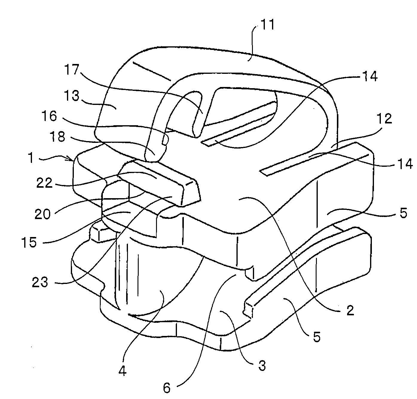
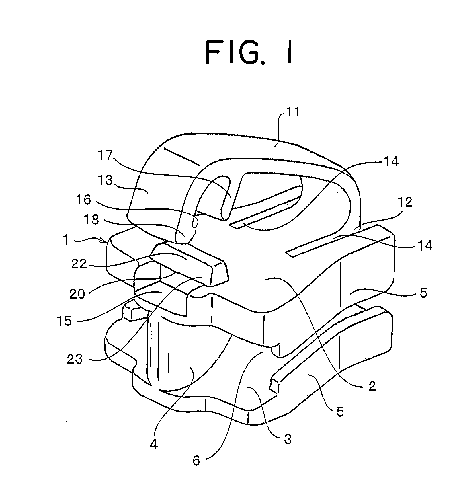
[0036]As shown in FIGS. 1 to 4, a slider for slide fastener of the type that a pull tab is to be attached afterward, in accordance with a first embodiment of the present invention, includes a body 1 and a pull tab attaching lever 11 provided on the top surface of the body 1. The body 1 and the pull tab attaching lever 11 are molded with a thermoplastic resin such as polyacetal, polyamide, polypropylene, or polybutylene terephthalate by injection molding means. As for the configuration of the body 1 of the slider, an upper blade 2 and a lower blade 3, which are disposed opposing vertically, are connected by a diamond 4 on a shoulder mouth 8 side, that is, on the front end side of the body 1, and flanges 5 are provided on both sides of the upper blade 2 and the lower blade 3 such that they project toward the lower blade 3 or the upper blade 2. The guide groove 6 is formed within the slider so as to be surrounded by the upper blade 2, the lower blade 3, the diamond 4 and the flanges 5....

second embodiment

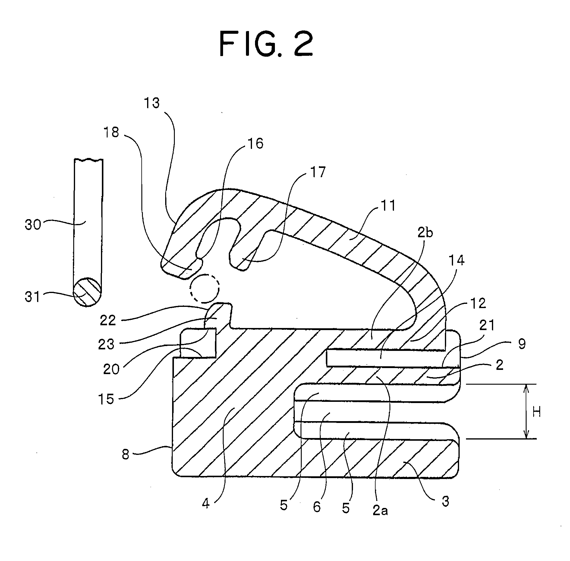
[0042]A slider for slide fastener of the type that a pull tab is to be attached afterward, in accordance with a second embodiment shown in FIG. 5, is invented by improving the projecting portion 17 of the pull tab attaching lever 11 and the projecting piece 22 formed on the top surface of the diamond 4 in the slider shown in the first embodiment. Other configuration is the same as that of the slider of the first embodiment. If speaking of the second embodiment, a hook portion 18 facing inward is provided at a front end portion 13 of the pull tab attaching lever 11, and an engaging portion 16 is formed on the top surface of the hook portion 18. Then, the projecting portion 17 disposed in parallel to the front end portion 13 is projected from the pull tab attaching lever 11, and the projecting piece 22 provided on the top surface of the diamond 4 is sandwiched by the front end portion 13 and the projecting portion 17.

[0043]On the other hand, a recess 15 is provided in the top surface ...


PUM


Abstract

The present invention provides a resin-made slider of the type that a pull tab is to be attached afterward, wherein a cantilever pull tab attaching lever is provided from a rear mouth side of an upper blade toward a shoulder mouth and has an engaging portion at a front end portion thereof, an engaged portion is provided on the shoulder mouth of the body so that the engaging and engaged portions can be engaged with each other, a concave portion is provided in the upper blade from a proximal portion toward the shoulder mouth, a gap portion is formed between the upper blade and the proximal portion, and the gap portion allows to form in the upper blade a first upper blade portion separated from the proximal portion and a second upper blade portion disposed from the proximal portion toward the shoulder mouth side and connected to the proximal portion.

Description

BACKGROUND OF THE INVENTION[0001]1. Field of the Invention[0002]The present invention relates to a slider for slide fastener of the type that a pull tab is to be attached afterward, which allows suppliers who deal clothes, bags or the like to easily attach a pull tab of his or her desired design or brand to a slider body made of a resin in which a pull tab attaching lever is formed integrally, the pull tab attaching lever having plasticity.[0003]2. Description of the Related Art[0004]A slider for slide fastener made of a resin, in which a pull tab can be attached to a slider body 101 formed preliminarily, is conventionally known as follows. As shown in FIG. 6, an attaching arm 133 with plasticity is projected in a shape of a cantilever from the top surface of a diamond 104 on a shoulder mouth 108 side of the slider body 101 while an engagement groove 130 having an arrow shaped section is provided at the front end of the arm 133. An engaging piece 122 having an umbrella shaped sectio...

Claims


Application Information

Patent Timeline
IPC IPC(8): A44B19/26A44B19/24
CPCA44B19/26Y10T24/2586Y10T24/2561
Inventor YAMAGISHI, KOJITAKE, HIDEYA
Owner YKK CORP
Why Eureka
Try Eureka