Fuel cell

a fuel cell and cell technology, applied in the field of fuel cells, can solve the problems of increased thickness of fuel cell units, difficulty in forming gas sealing members, loss of sealing performance, etc., and achieve the effect of improving sealing performan

Inactive Publication Date: 2005-03-15
HONDA MOTOR CO LTD
View PDF8 Cites 6 Cited by
  • Summary
  • Abstract
  • Description
  • Claims
  • Application Information

AI Technical Summary

Benefits of technology

The present invention was conceived in view of the above circumstances, and it is an object thereof to provide a fuel cell whose dimension in the stacking direction is restrained while ensuring sealing performance, and in which the sealing performance may be further improved by forming the gas sealing member integrally with the separator.
According to the fuel cell as constructed above, in the one separator, because the reaction gas communication ports are connected with the reaction gas flow passages by the through paths, the reaction gas communication paths need not be formed therein. Therefore, because a gap accompanied with the communication paths may not be formed on the front surface (the surface forming the reaction gas flow passage) of the separator, the portion, between the reaction gas communication ports and reaction gas flow passage, where the gas sealing member is formed can be made flat. As a result, the leakage of the material of the gas sealing member during formation thereof can be prevented, the deformation of the gas sealing member can be prevented, the gas sealing member can be securely bonded to the predetermined position on the separator, and thus the sealing performance of the gas sealing member is improved. Moreover, the reaction gas flow passage can be sealed in a fluid tight state by making the gas sealing member formed on the one separator and the gas sealing member bonded to the electrolyte of the electrode assembly be pressed against the other separator.
In addition, in the other separator, the reaction gas need not flow along the rear surface (the surface to be cooled) of this separator because the reaction gas communication ports are connected with the reaction gas flow passage by the communication paths, accordingly, the cooling surface sealing member need not be formed at a position overlapping, as viewed in the stacking direction, with the reaction gas flow passage. As a result, by providing the cooling surface sealing member so as to be offset, as viewed in the stacking direction, from the reaction gas flow passage, the dimensions of the fuel cell units, consequently, the dimensions of the fuel cell stack in the stacking direction can be reduced by the amount saved by the above-mentioned offset disposition.
According to the fuel cell as constructed above, a portion of the electrolyte that extends out of the electrode (smaller electrode) contacting the one separator can be supported, in the thickness direction thereof, by the electrode (larger electrode) contacting the other separator. It is possible to bond the gas sealing member to the one separator so that the gas sealing member contacts the supported portion of the electrolyte. As a result, the gas sealing member can be pressed against the electrolyte while ensuring the strength of the electrolyte in the thickness direction thereof.
If the supported portion is made of sealing material instead of a material for the electrode, the sealing performance at the portion can be further improved. The planar area of the electrolyte may be formed larger than that of the larger electrode, or may be formed as large as that of the larger electrode. If the planar area of the electrolyte is larger than that of the larger electrode, the gas sealing member may be bonded to the peripheral portion of the electrolyte.
According to the fuel cell as constructed above, by making the gas sealing member be pressed against the electrode assembly, the leakage of the reaction gas from the space delimited by the electrode assembly can be prevented, and by making the gas sealing member be pressed against the other separator, the leakage of the reaction gas to the outside can also be prevented.

Problems solved by technology

The drawback with this structure is that sealing performance may be lost if the gas sealing members 8 and 9 are deformed in the gap 14 when the gas sealing members 8 and 9 are attached onto the separators 2 and 3 and the bridge plate 13.
Moreover, another drawback is that it is very difficult to form the gas sealing members 8 and 9 on the separators 2 and 3 and the bridge plate 13, because the material of the gas sealing members 8 and 9 may leak through the gap 14.
However, in such a structure, a problem is experienced in that, because reaction gas flow passages must be formed between the adjacent separators not only on the front surface of the separator but also on the rear surface thereof in order to allow the reaction gas to flow from the gas flow passage on the rear surface (cooling surface) to the gas flow passage on the front surface or vice versa, the thickness of the fuel cell units may be increased by the amount necessary to form these flow passages.
If a fuel cell stack is formed by stacking a plurality of such fuel cell units, the overall thickness of the fuel cell stack is found by multiplying the number of stacks by the minimum thickness of each fuel cell unit, which makes it difficult to reduce the size of the fuel cell stack.

Method used


Image

  • Fuel cell
  • Fuel cell
  • Fuel cell

Examples


Embodiment Construction

The fuel cell stack according to an embodiment of the present invention will now be described in detail with reference to the drawings.

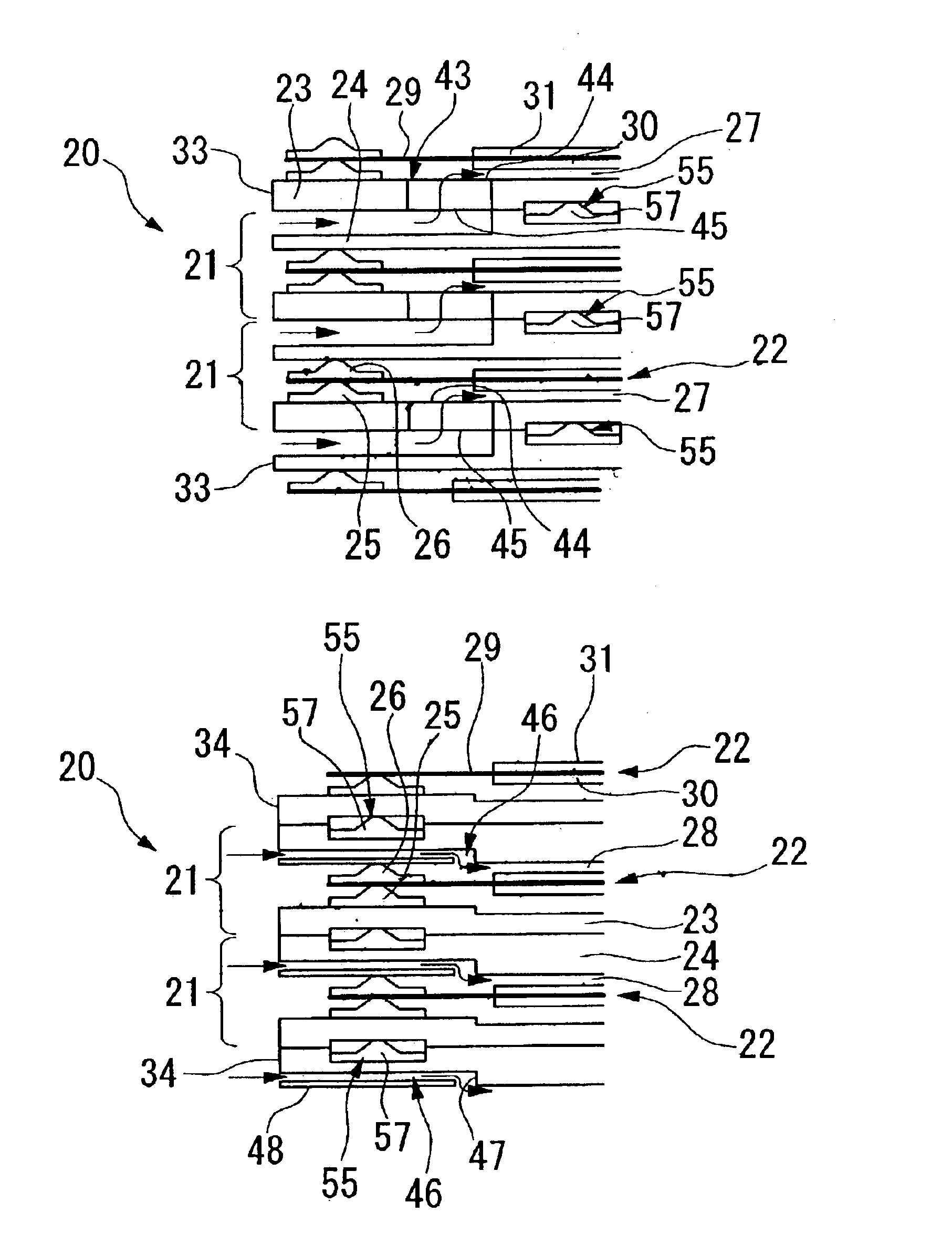
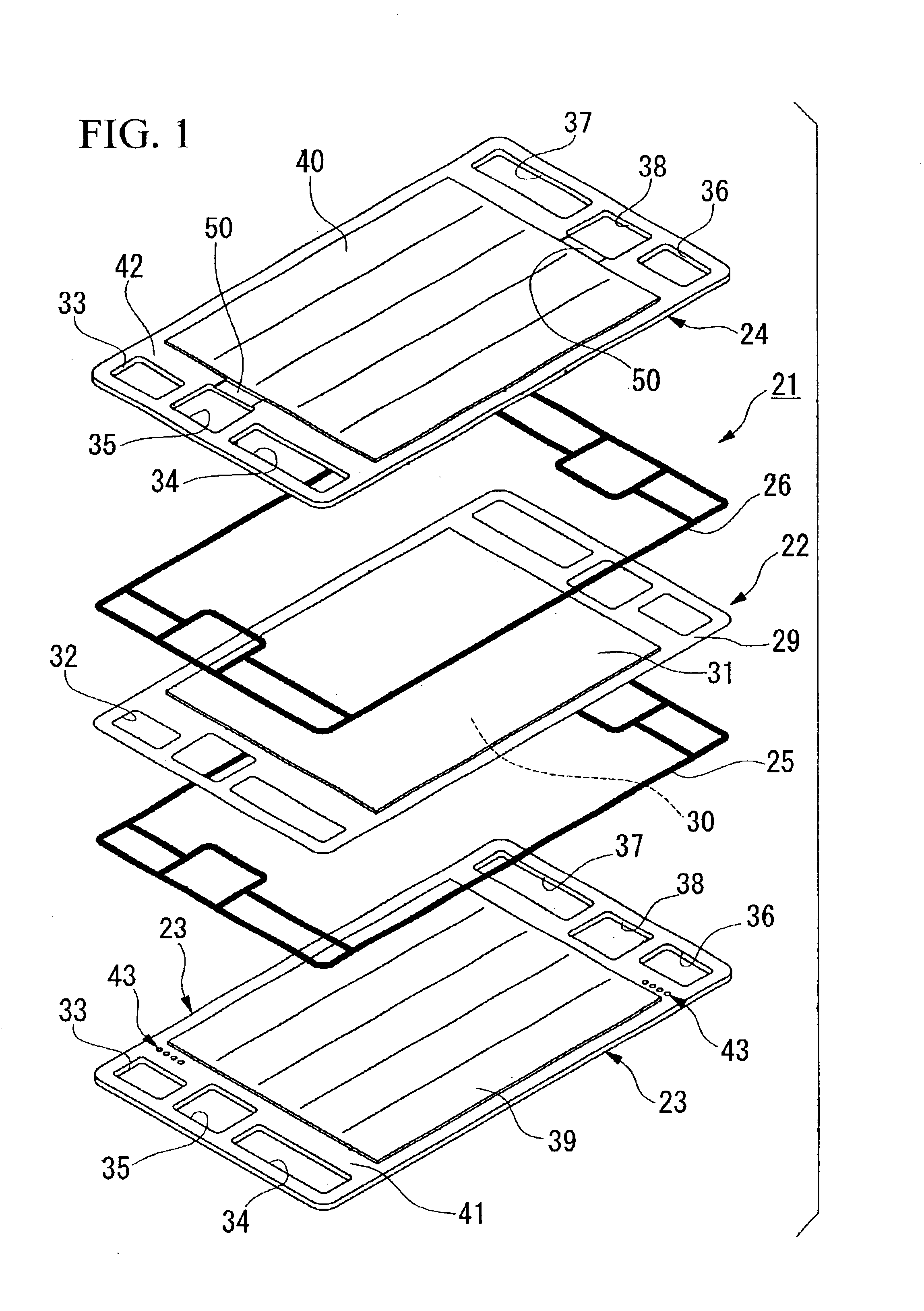
As shown in FIG. 12, the fuel cell stack 20 according to the present embodiment is formed by stacking a plurality of fuel cell units 21. As shown in FIG. 1, the fuel cell unit 21 is formed by sandwiching an electrode assembly 22 between a pair of separators 23 and 24. Between the electrode assembly 22 and each of the separators 23 and 24 are disposed respectively gas sealing members 25 and 26. As shown in FIGS. 12 and 13, these gas sealing members 25 and 26 delimit a fuel gas flow passage 27 and an oxidizing gas flow passage 28 so as to seal them on either side of the electrode assembly 22.

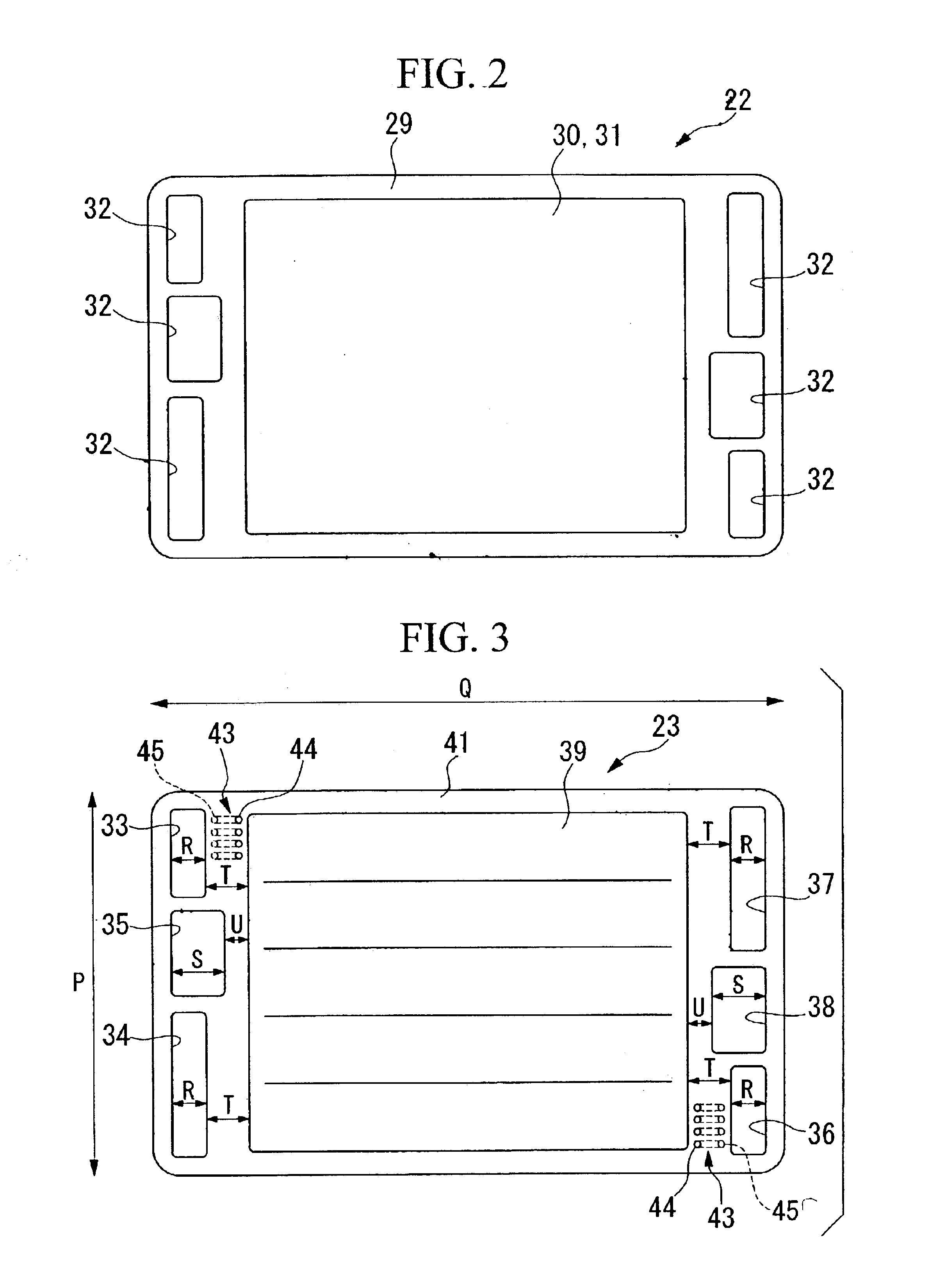
As shown in FIGS. 2 and 12, the electrode assembly 22 has, for example, a solid polymer electrolyte membrane 29 (hereinafter simply referred to as an electrolyte membrane) formed from a perfluorosulfonate polymer, and an anode electrode 30 and cathode electrode 31 ...


PUM

PropertyMeasurementUnit
thicknessaaaaaaaaaa
thicknessaaaaaaaaaa
widthaaaaaaaaaa

Abstract

A fuel cell is provided that has a sufficient sealing performance while having a restrained dimension in the stacking direction thereof. The fuel cell is formed by stacking a plurality of fuel cell units, each fuel cell unit comprising: an electrode assembly formed by disposing electrodes on both sides of an electrolyte; a pair of separators that sandwich the electrode assembly in the thickness direction thereof; and gas sealing members that are disposed at an outer peripheral portion of the electrode assembly, and that seal respective reaction gas flow passages that are formed between each separator and the electrode assembly and are bounded by the separators and electrode assembly. In each of the separators, there are provided reaction gas communication ports that are provided outward from the gas sealing members, in one separator, through paths are formed that penetrate the separator in the thickness direction thereof and connect the reaction gas communication ports with the reaction gas flow passages, and in the other separator, reaction gas communication paths are formed that detour around the gas sealing member in the thickness direction of the separator and connect the reaction gas communication ports with the reaction gas flow passages.

Description

BACKGROUND OF THE INVENTION1. Field of the InventionThe present invention relates to a fuel cell formed by stacking a plurality of fuel cell units that are formed by sandwiching an electrode assembly between separators.2. Description of the Related ArtAmong fuel cell units, there is one type that is formed in a plate shape by sandwiching between a pair of separators an electrode assembly that is formed by placing an anode electrode and a cathode electrode respectively on either side of a solid polymer electrolyte membrane. A fuel cell is formed by stacking in the thickness direction of the fuel cell units a plurality of fuel cell units that are structured in this way.In each fuel cell unit there is provided a flow passage for fuel gas (for example, hydrogen) on the surface of the anode side separator that is positioned facing the anode electrode, and there is provided a flow passage for oxidizing gas (for example, air that contains oxygen) on the surface of the cathode side separato...

Claims


Application Information

Patent Timeline
Patent Type & Authority Patents(United States)
IPC IPC(8): H01M2/08H01M8/10H01M8/02H01M8/24H01M8/04
CPCH01M8/0258H01M8/0273H01M8/04089Y02E60/50H01M2008/1095H01M8/04029H01M8/2483H01M8/241H01M8/0267H01M8/0271
Inventor KIKUCHI, HIDEAKISUGITA, NARUTOSHINAKANISHI, YOSHIHIRONISHIYAMA, TADASHIANDOU, KEISUKE
Owner HONDA MOTOR CO LTD
Why Eureka
Try Eureka