Precision machining method for high-precision U-shaped low-rigidity bearing block type parts

A precision machining and weak stiffness technology, applied in the field of precision machining, can solve problems such as uneven distribution of cutting amount, difficulty in accurately controlling cutting amount, large elastic deformation, etc., to avoid AA dimension out-of-tolerance, reduce chattering problems, The effect of increasing the rigidity of the part

Active Publication Date: 2017-03-22
INST OF OPTICS & ELECTRONICS - CHINESE ACAD OF SCI
View PDF4 Cites 5 Cited by
  • Summary
  • Abstract
  • Description
  • Claims
  • Application Information

AI Technical Summary

Problems solved by technology

[0010] The main technical difficulties of precision machining are due to the poor rigidity of the parts, large elastic deformation during processing, and serious vibration of the parts, which makes it difficult to accurately control the actual cutting amount, and the actual cutting amount is unevenly distributed, resulting in difficulty in the size and shape accuracy of the parts. Guaranteed, low parts pass rate

Method used


Image

  • Precision machining method for high-precision U-shaped low-rigidity bearing block type parts
  • Precision machining method for high-precision U-shaped low-rigidity bearing block type parts
  • Precision machining method for high-precision U-shaped low-rigidity bearing block type parts

Examples


specific Embodiment

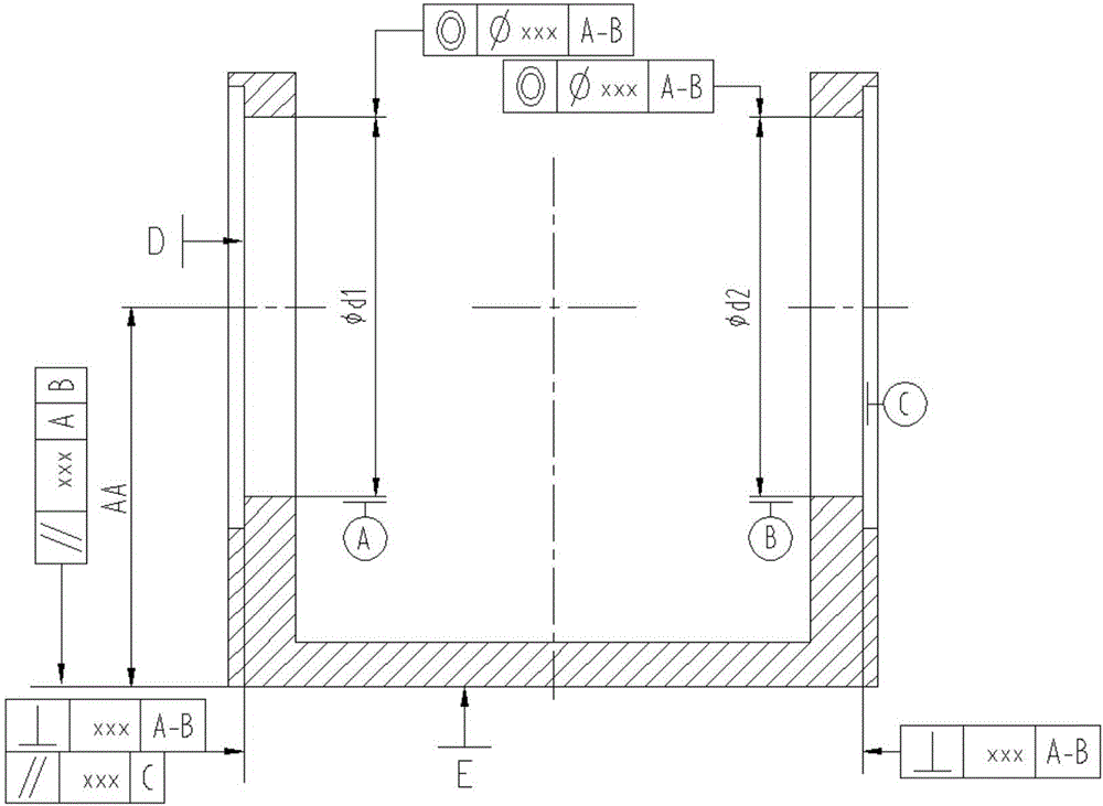
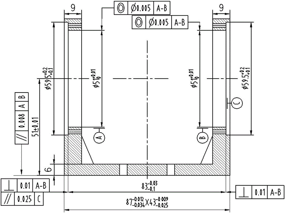
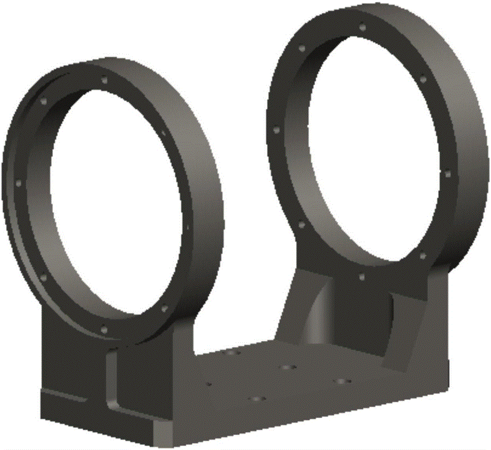
[0052] as attached figure 2 , 3 The material of the high-precision U-shaped weak rigidity bearing seat part shown is TC4R, and its precision machining method includes the following steps:

[0053] Step 1), preparing materials;

[0054] Step 2), rough machining, machining the parts into shape, leaving a margin of 2 mm for one side and radius of all shapes;

[0055] Step 3), vacuum stress relief aging;

[0056] Step 4), semi-finishing, processing each feature of the part, including 51±0.01 lower end surface, two places hole, both ends, A margin of 0.4mm is left on one side of the four sides and the radius, two 8-M2-7H are not processed, and the rest of the features are processed to meet the size requirements of the drawing;

[0057] Step 5), vacuum stress relief aging;

[0058] Step 6), process 1: fine boring 51±0.01 lower end face, The size requirements of the four-sided map, guarantee: 51±0.01 lower end surface flatness ≤0.01mm; if attached Figure 4 As shown, th...


PUM


Abstract

The invention discloses a precision machining method for high-precision U-shaped low-rigidity bearing block type parts. The method comprises steps as follows: 1, materials are prepared; 2, rough machining is performed, the parts are machined and shaped, and all outlines reserve the machining allowance; 3, stress ageing is eliminated, and the residual stress produced by rough machining is eliminated; 4, semi-finish machining is performed, and except that assembling datum surfaces, mounting holes of bearings, end surfaces of the bearings and important mounting connecting holes reserve the machining allowance, other machining characteristics meet size requirements; 5, stress ageing is eliminated again, and the residual stress produced by semi-finish machining is eliminated; 6, finish machining is performed on the assembling datum surfaces, the mounting holes of the bearings, the end surfaces of the bearings and the important mounting connecting holes. The datum-uniform and datum-first principles are adopted in the process, auxiliary tools are designed to reduce trembling and improve the rigidity of the parts, meanwhile, the influence of machining elastic deformation is considered in control on central high sizes, and certain correction margins are reserved. With the method, the percent of pass of the high-precision U-shaped low-rigidity bearing block type parts is guaranteed.

Description

technical field [0001] The invention belongs to the technical field of precision machining, and in particular relates to a precision machining method for high-precision U-shaped low-rigidity bearing seat parts. Background technique [0002] High-precision U-shaped low-rigidity bearing housing parts are widely used in aerospace products, and its main features are: high precision, poor rigidity, and light weight. At present, the commonly used materials mainly include aluminum alloy and titanium alloy. [0003] Key accuracy specifications for such parts typically include: [0004] First, the roundness, cylindricity, coaxiality and size of the two bearing mounting holes; [0005] Second, the parallelism between the axes of the two bearing mounting holes and the assembly reference plane of the parts; [0006] Third, the distance between the axis of the two bearing mounting holes and the assembly reference plane of the part; [0007] Fourth, the perpendicularity between the en...

Claims


Application Information

Patent Timeline
Patent Type & Authority Applications(China)
IPC IPC(8): B23P15/00
CPCB23P15/003
Inventor 安祥波余伦高七一涂文英蒋文理
Owner INST OF OPTICS & ELECTRONICS - CHINESE ACAD OF SCI
Why Eureka
Try Eureka