Ductless dryer

a dryer and ductless technology, applied in the direction of drying machines, drying machines, light and heating equipment, etc., can solve the problems of inability to use gas as heating source in the room in which the dryer is situated, and the noise in the room may not be quiet, so as to achieve the effect of attenuating the nois

Inactive Publication Date: 2008-08-21
LG ELECTRONICS INC
View PDF2 Cites 18 Cited by
  • Summary
  • Abstract
  • Description
  • Claims
  • Application Information

AI Technical Summary

Benefits of technology

[0011]To achieve these and other advantages and in accordance with the purpose of the present invention, as embodied and broadly described herein, there is provided a ductless dryer including: a main body; a drum rotatably installed at the main body; a heat exchanger for removing moisture included in air exhausted from the drum; a circulation duct to conduct the air exhausted from the drum to the heat exchanger; an exhaust duct to conduct the air exhausted from the heat exchanger outside the dryer; and a noise reduction portion to attenuate noise from being propagated through the exhaust duct.
[0012]Herein, preferably, the noise reduction portion may be installed between the circulation duct and the heat exchanger in consideration of space limitations. Further, preferably, the noise reduction portion is connected with the heat exchanger in a straight line in order for the air from the noise reduction portion to be directly introduced to the heat exchanger. Further, preferably, in the noise reduction portion, first, second and third pipes are sequentially connected, and a cross-sectional area of the second pipe is larger than the cross-sectional areas of the other pipes, the first and the third pipes.
[0013]Herein, more preferably, the first and the third pipes have the same cross-sectional area as each other.
[0014]Further, preferably, the noise loss transfer function (LT) through the noise reduction portion can be determined by the following formula:
[0015]Meanwhile, the noise reduction portion may include an inner pipe; and an outer pipe enclosing the inner pipe to form a noise space, and the inner pipe may be provided with a plurality of noise openings therein in communication with the noise space. Herein, preferably, the outer pipe entirely or partly encloses the inner pipe. If the outer pipe encloses only a part of the inner pipe, the enclosing angle (Θ) is 120° or less, preferably. Herein, preferably, the outer pipe includes an outer wall enclosing the inner pipe and being spaced therefrom in a radial direction; and lateral walls forming the noise space by closing front and rear ends of the outer wall. Further, preferably, the target noise frequency to be attenuated through the noise reduction portion is determined by the following formula.

Problems solved by technology

However, a condensing type dryer does not facilitate to use gas as a heating source because a closed loop may be formed due to the recirculating flowing of the drying air.
However, in the case of the ductless dryer, because the exhaust duct is exposed into the room, accordingly noise may emanate into the room through the exhaust duct, and thereby, the room in which such ductless dryer is situated may not be quiet.

Method used


Image

  • Ductless dryer
  • Ductless dryer
  • Ductless dryer

Examples


first embodiment

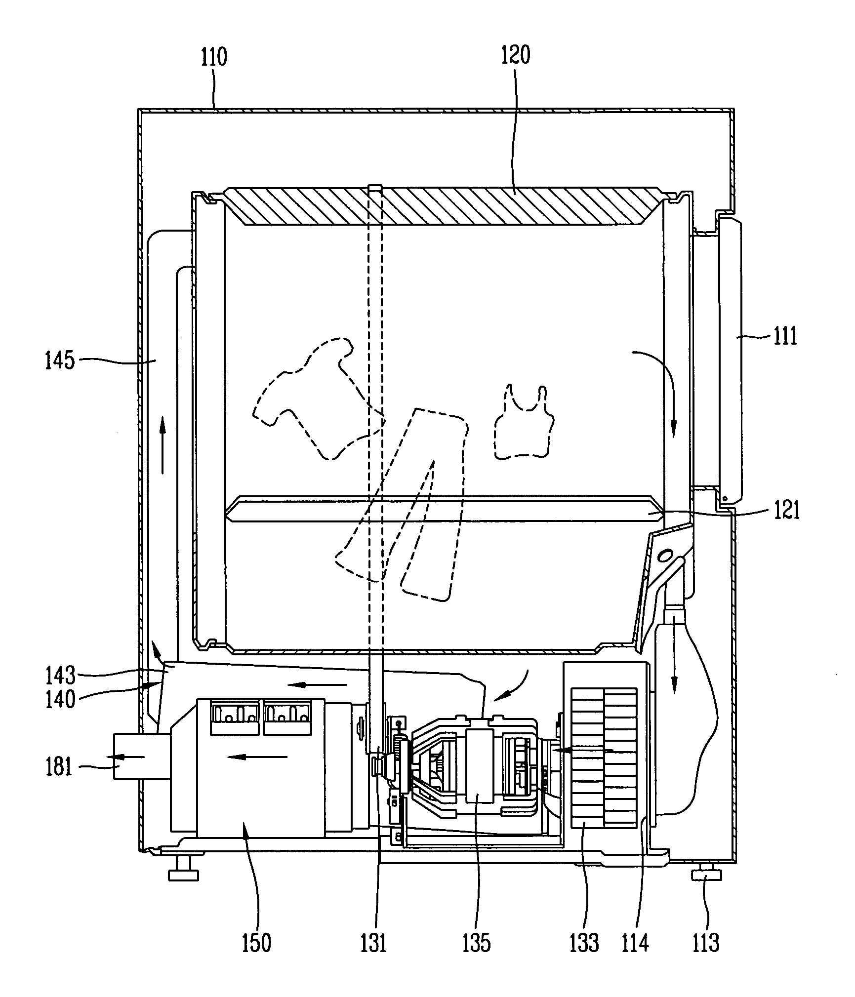
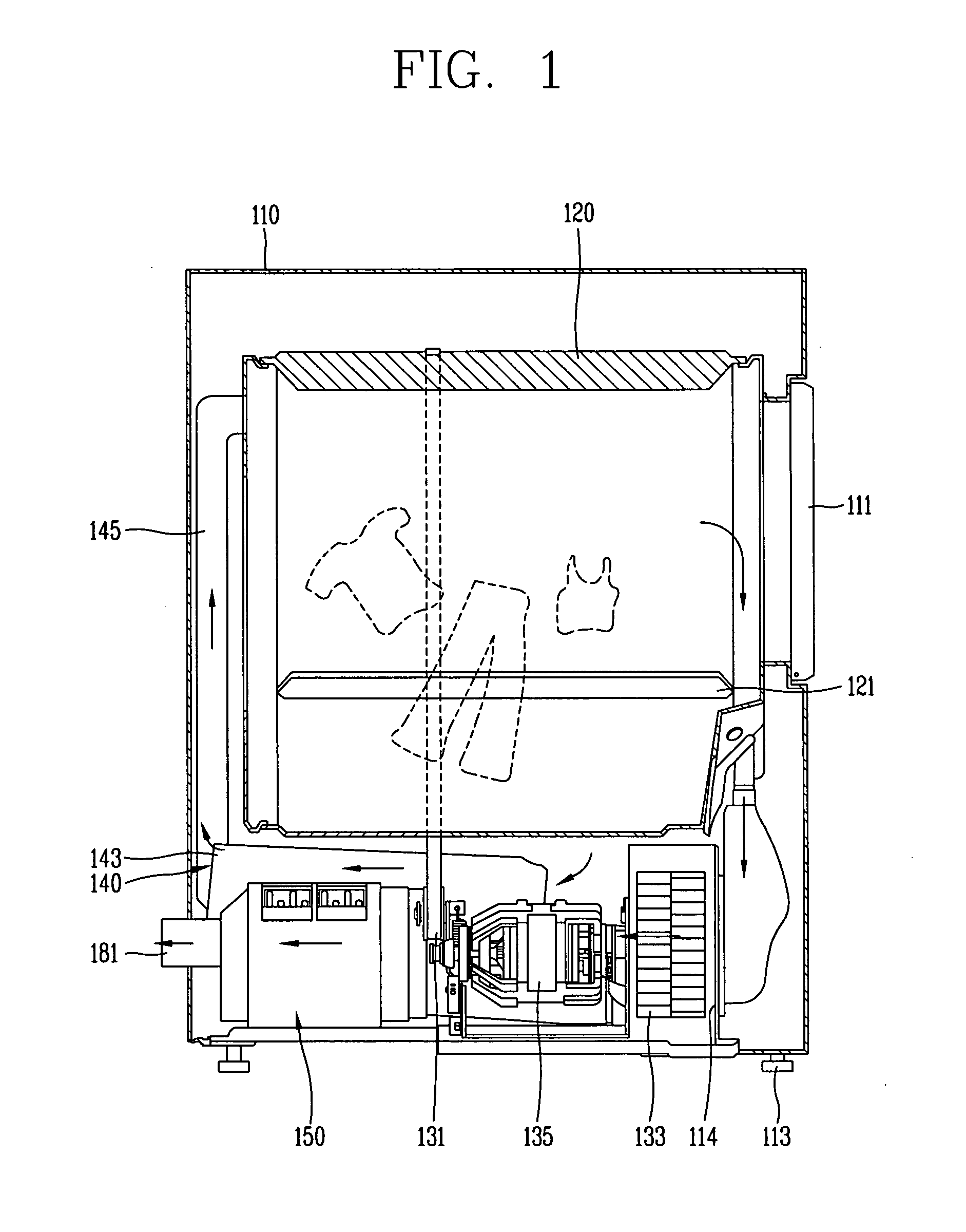
[0030]Referring to FIGS. 1 and 2, the ductless dryer having the noise reduction portion in accordance with the present invention includes a main body 110, a drum 120 rotatably installed at the main body 110, a hot air supplying unit 140 providing hot air into the drum 120, a heat exchange unit 150 condensing moisture included in the air exhausted from the drum 120 through heat exchange with cooler exterior air, a circulation duct 114 conducting the air exhausted from the drum 120 to the heat exchange unit 150, an exhaust duct 181 conducting the air exhausted from the heat exchange unit 150 outside the dryer, and a noise reduction portion 160 for attenuating noise so as to prevent the noise from being transferred through the exhaust duct 181. Herein, the noise reduction portion 160 may be installed between the circulation duct 114 and the heat exchange unit 150 in consideration of a limitation of space inside the dryer. Further, the noise reduction portion 160 may be connected inline...

second embodiment

[0049]FIG. 9 is a perspective schematic diagram showing a noise reduction portion in accordance with the present invention and a noise level test setup therefor, FIG. 10 is a diagram showing a cross-section X-X of the noise reduction portion in FIG. 9, FIG. 11 is a diagram showing a cross-section XI-XI of the noise reduction portion in FIG. 9, and FIG. 12 is a graph comparing results of noise level measurements according to varying the number of noise reduction portion exhaust openings in the noise reduction portion in FIG. 9.

[0050]Referring to FIGS. 9 and 10, the noise reduction portion 170 in accordance with the second embodiment of the present invention includes an inner pipe 171 and an outer pipe 173 forming a space S by enclosing a part of or the entire inner pipe 171. A plurality of openings 171a in communication with the space S are formed in the surface of the inner pipe 171.

[0051]Preferably, the outer pipe 173 encloses the entirety or a part of the inner pipe 171 so as to e...


PUM


Abstract

A ductless dryer includes a main body, a drum rotatably installed at the main body, a heat exchanger for removing moisture from air exhausted from the drum, a circulation duct to flow the air exhausted from the drum into the heat exchanger, an exhaust duct to flow the air exhausted from the heat exchanger outside the dryer; and a noise reduction portion to attenuate noise propagation through the exhaust duct. As the ductless dryer is provided with the noise reduction portion, the noise propagation through the exhaust duct exposed into the room and the noise of the entire ductless dryer can be attenuated at the same time, whereby a quieter room environment can be provided.

Description

[0001]This application claims the benefit of the Korean Patent Application No. 10-2007-0017172, filed on Feb. 20, 2007, which is hereby incorporated by reference in its entirety as if fully set forth herein.BACKGROUND[0002]1. Field of the Invention[0003]The present invention relates to a ductless dryer, and particularly, to a ductless dryer in which noise is attenuated completely by attenuating the noise transferred through an exhaust duct exposed into a room.[0004]2. Description of the Related Art[0005]In general, a dryer, e.g. a clothes dryer, is an apparatus performing a drying operation on objects such as wet laundry to be dried by blowing hot air generated by a heater into a drum to absorb moisture from the objects therewithin. Dryers can be categorized as exhausting (e.g. vented) type dryers and condensing (e.g. ventless) type dryers depending on the method employed for dealing with the humid air generated as the objects are dried by absorbing moisture therefrom.[0006]In the e...

Claims


Application Information

Patent Timeline
Patent Type & Authority Applications(United States)
IPC IPC(8): D06F58/04E04F17/04
CPCD06F58/20D06F58/04D06F58/00
Inventor JUNG, HAN-YONGAHN, SEUNG-PHYOLEE, SANG-IKJUNG, KYUNG-MUNEOM, YOON-SEOBKIM, YANG-HOWEE, JEA-HYUKRYOO, BYEONG-JOSONG, SUNG-HO
Owner LG ELECTRONICS INC
Why Eureka
Try Eureka