
Electrically Driven Entryway Actuation System

Inactive Publication Date: 2008-08-21
WABTEC HLDG CORP
View PDF13 Cites 7 Cited by
  • Summary
  • Abstract
  • Description
  • Claims
  • Application Information

AI Technical Summary

Benefits of technology

[0008]Briefly, according to this invention, there is provided an electrically driven entryway actuation system which includes a base plate, a prime mover at the center of the base plate, a first pivot assembly connected to a first door, a second lever assembly connected to a second door, a first adjustable rod connecting the first lever assembly to the prime mover, a second adjustable rod connecting the second lever assembly to the prime mover, an emergency release mechanism connected to the prime mover, and a remote emergency release lever attached to the emergency release mechanism. The configuration of each of the above elements has been arranged for maximum space efficiency and to ensure that all motion occurs in a single plane of action. This allows the system to reduce inefficiency of operation, leading to a lower operational heat build-up, and reduced stress and strain on both the actuator mechanism and the bus frame.

Problems solved by technology

Both of these prior art systems fail to efficiently use space and require motion in more than one plane of action.

Method used


Image

  • Electrically Driven Entryway Actuation System
  • Electrically Driven Entryway Actuation System
  • Electrically Driven Entryway Actuation System

Examples


Embodiment Construction

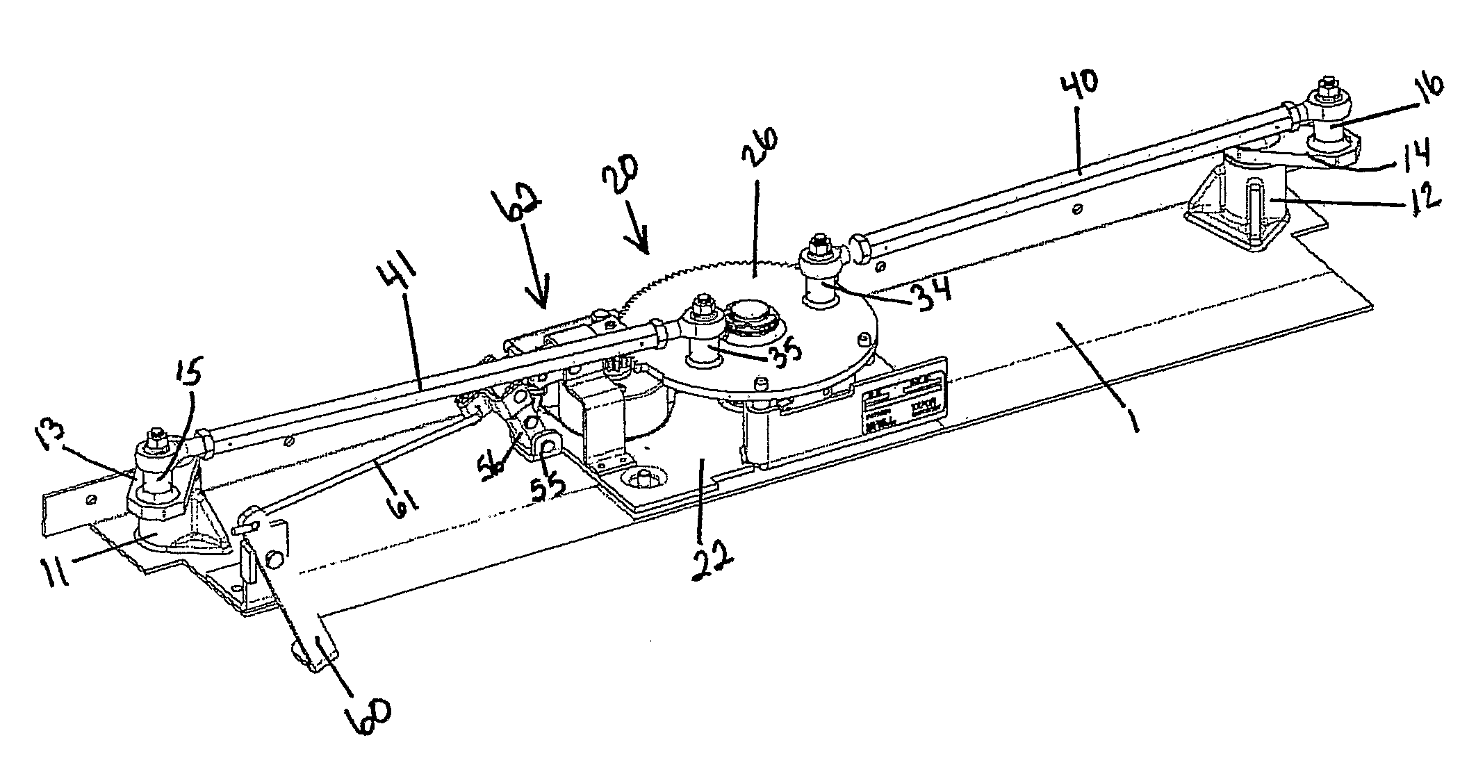
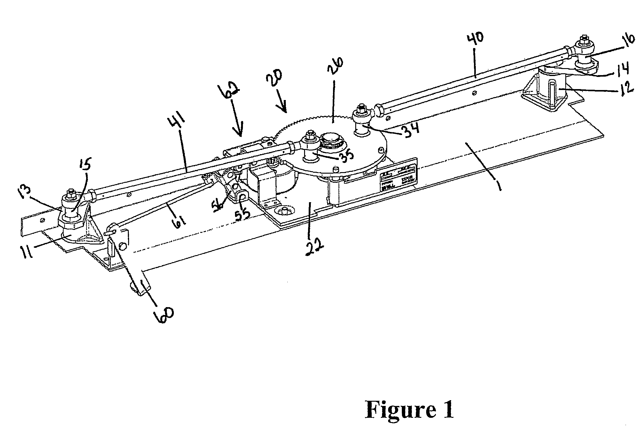
[0021]Referring to FIG. 1, the electrically driven entryway activation system for opening and closing two spaced swinging doors is shown. At each end of a base plate 10 mounted above the door opening are located hubs 11, 12 that journal the rotating door posts (not shown). Levers 13, 14 are fixed to each rotating door post. Extending from the levers 13, 14 are pivot posts 15, 16 which have an axis parallel with the door posts. The levers rotate in a plane parallel with the base plate 10.

[0022]The hubs 11, 12 are preferably cast steel components that are welded to the base plate 10. A flange and supporting ribs may be present to help the device resist bending and reduce strain on welded joints. A bearing is inserted in the hubs for journaling the door posts.

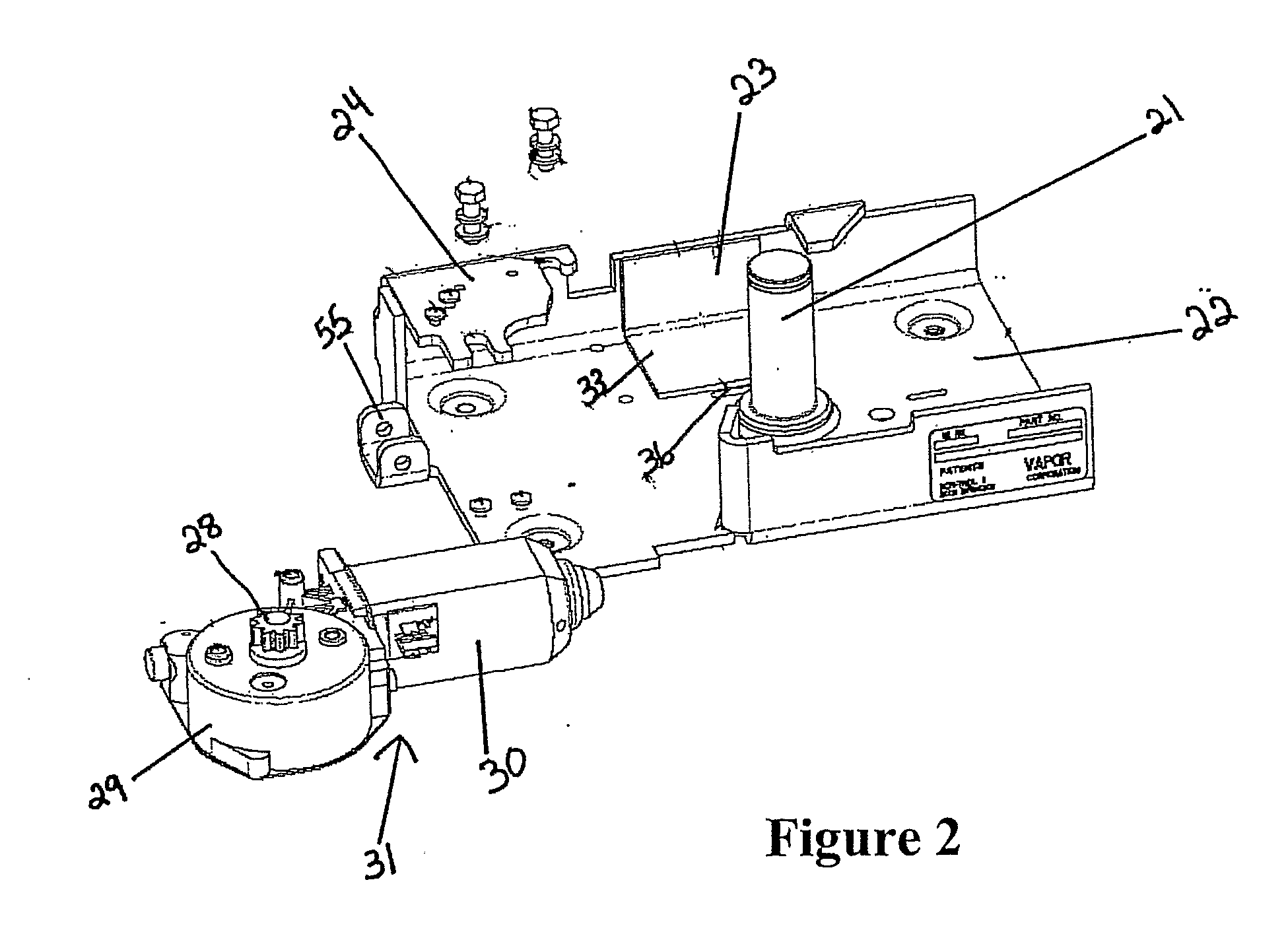
[0023]A low profile actuation system 20 is fixed to the base plate between the hubs. The actuation means has a center post 21 supported relative to the base plate 10. The center post is parallel to the rotating door posts.

[0024]As...


PUM


Abstract

An electrically driven entryway activation system for opening and closing two spaced swinging doors hung on spaced rotating parallel door posts comprises a base plate extending between the door posts. Levers attached to each door post rotate in a plane parallel to the base plate. A low profile actuation system spaced between the levers comprises a center post, a sector gear journaled on the center post for rotation parallel to the base plate, and a low profile gearmotor mounted between the base plate and the sector gear. A low profile emergency manual mechanism is provided for unclutching the output pinion gear of the gearmotor.

Description

BACKGROUND OF THE INVENTION[0001]1. Field of the Invention[0002]The present invention relates, in general, to an electric actuator and, more specifically, to an electric actuator for opening and closing the door to a vehicle.[0003]2. Description of Related Art[0004]Power door operators have been developed to reduce the strain on vehicle operators caused by the repeated opening and closing of vehicle doors. Many power door operators use pneumatic actuators because the air brake systems in mass transit vehicles provide a reliable and convenient source of air at controlled pressure. U.S. Pat. No. 4,454,685 is an example of such a power door operator.[0005]Electric door actuators have also been developed. U.S. Pat. No. 5,332,279 discloses a power door operator for multi-passenger mass transit vehicles. This system uses electrical gear motor operating drive arms in order to open and close dual panel swing door sets. U.S. Pat. No. 6,125,768 discloses a door system for transit vehicles tha...

Claims


Application Information

Patent Timeline
IPC IPC(8): E05F15/02
CPCE05F17/004E05Y2201/214E05Y2201/244E05Y2201/434E05Y2600/522E05F15/63E05Y2800/25E05Y2800/73E05Y2900/51E05F15/603E05Y2800/232B60J5/0411B60J5/047
Inventor BROWN, CARY L.
Owner WABTEC HLDG CORP
Learn More