

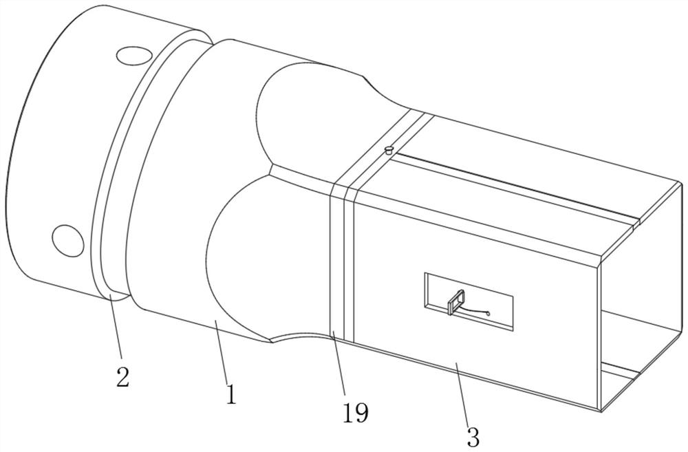
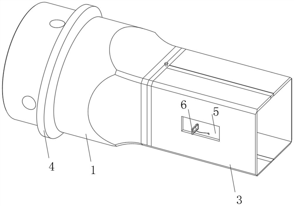
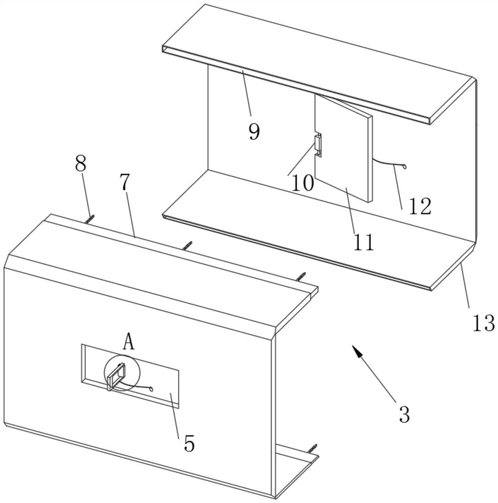
Welding method for manually welding small groove of T-shaped welding seam and matched welding gun nozzle
A technology of groove welding and welding method, which is applied in the field of welding and steel welding, and can solve the problems of welding application and popularization of narrow gap welding technology, unrealistic application of machining grooves in large areas, and increased cost of groove machining, etc. Achieve the effect of reducing stress and strain, reducing welding cost and improving welding efficiency
- Summary
- Abstract
- Description
- Claims
- Application Information
AI Technical Summary
Problems solved by technology
Method used
Image

Examples
Embodiment 1
[0058] Step 1: Make the groove of the steel plate to be welded, and open the groove below any welding end of the two steel plates to be welded;
[0059] Step 2: The opening angle of the groove at the welding end of the steel plate is 20°, the distance between the bottom of the groove and the bottom of the welding end of another steel plate is 6mm, and the thickness of the steel plate is 40mm;
[0060] Step 3: Weld the bevel end of the steel plate prepared in Step 1 and Step 2 with carbon dioxide welding equipment using matching torch nozzles.
[0061] In step 3, the welding voltage U=35V, the current I=290A, the gas flow rate is 18L / min, the welding speed is 40cm / min, and the groove welding is not preheated.
[0062] The base material is Q345C, and the welding wire is CHW-50C6 (ER50-6) produced by Atlantic Welding Wire Factory.
[0063] Technological test parameters:
[0064]
[0065] During the welding process, there are no defects such as air holes and cracks in the bot...
PUM
 Abstract
Description
Claims
Application Information