System Reheat Control by Pulse Width Modulation

a technology of pulse width and reheat capacity, applied in the direction of lighting and heating apparatus, machine operation mode, heating type, etc., can solve the problems of not being utilized to provide varying steps in reheat capacity, and the refrigerant system designer is faced with challenges, and achieve the effect of overall system performan

Inactive Publication Date: 2008-08-21
CARRIER CORP
View PDF9 Cites 3 Cited by
  • Summary
  • Abstract
  • Description
  • Claims
  • Application Information

AI Technical Summary

Benefits of technology

[0006]In a disclosed embodiment of this invention, a pulse width modulation control is provided for selectively varying capacity provided by a reheat circuit and thus overall system performance. The “on / off” cycle time interval is selected such that the overall effect on the system in terms of external operational characteristics, due to system thermal inertia, is negligible. That is, an occupant of an environment being conditioned would not recognize that the flow of refrigerant to the reheat circuit is being periodically turned on and off.

Problems solved by technology

These contradicting trends presented challenges to refrigerant system designers.
While pulse width modulation controls have been provided for various purposes in refrigerant systems, they have not been utilized to provide varying steps in a reheat capacity.

Method used


Image

  • System Reheat Control by Pulse Width Modulation
  • System Reheat Control by Pulse Width Modulation

Examples


Embodiment Construction

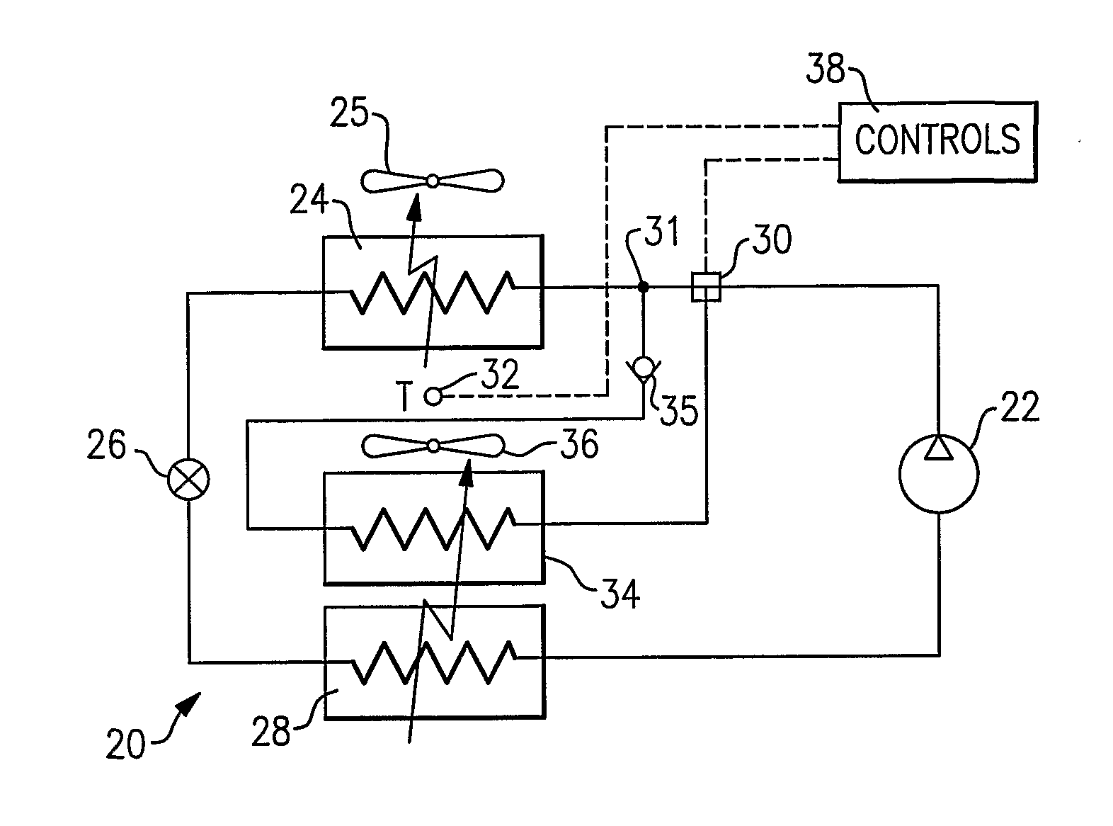
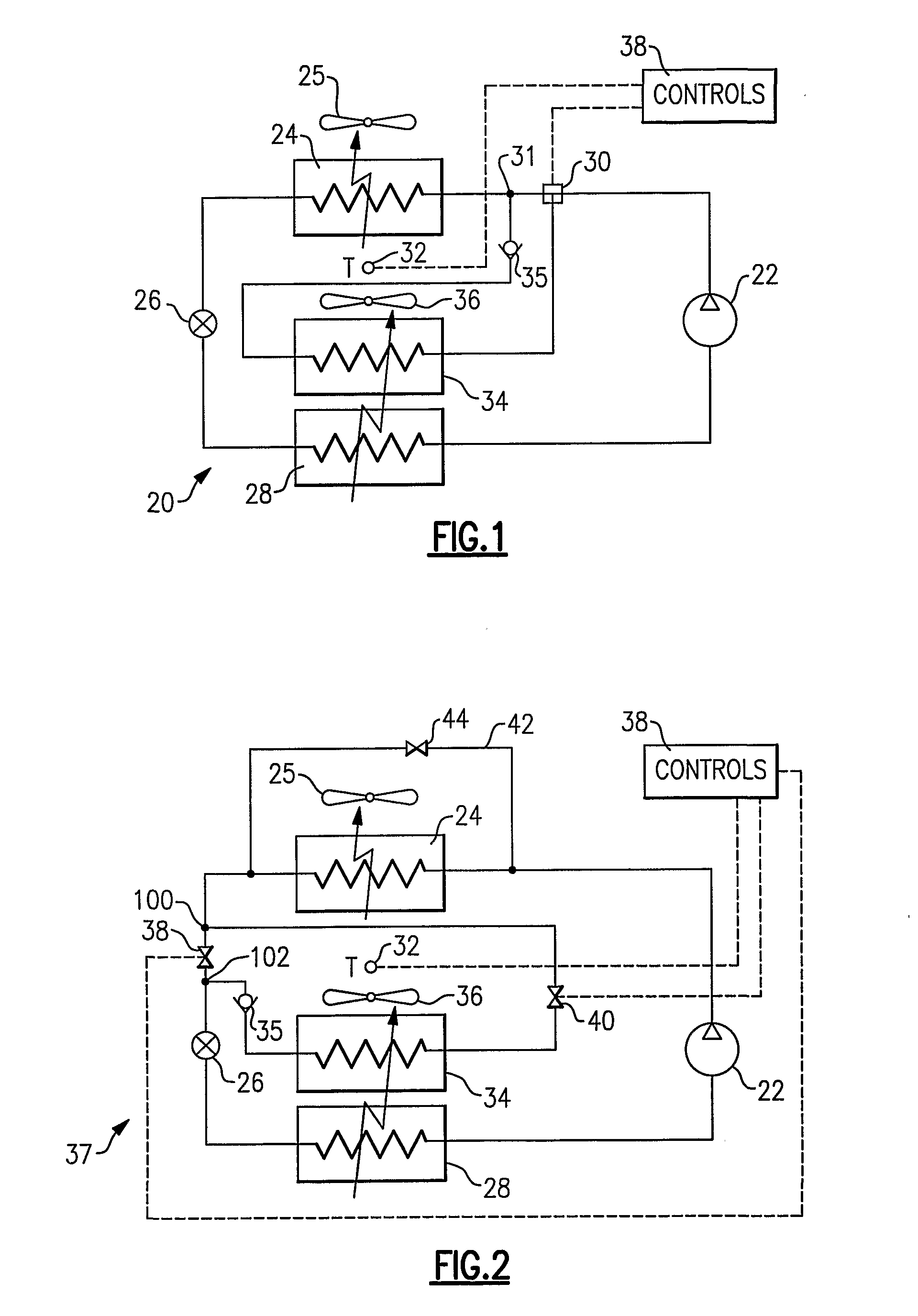
[0012]A refrigerant system 20 is illustrated in FIG. 1 including a compressor 22 compressing refrigerant and delivering it to a downstream condenser 24. A fan 25 blows air over the condenser 24. Refrigerant passes from the condenser 24 to a downstream expansion device 26, then to an evaporator 28, and finally returns to compressor 22. A three-way valve 30 is placed on a discharge refrigerant line, and as illustrated, between the compressor 22 and the condenser 24. The three-way valve 30 is controlled by a control 38 for a purpose that will be described below. When the three-way valve is in an open position, it will deliver refrigerant through a reheat heat exchanger 34 and a check valve 35, and then return the refrigerant back to a position 31 still upstream of the condenser 24. As is known, a fan 36 blows air over the evaporator 28, and the reheat heat exchanger 34 is placed such that it is in the path of that air stream behind the evaporator 28.

[0013]The purpose of the reheat heat...


PUM


Abstract

A refrigerant system is provided with a reheat circuit. A pulse width modulation control is provided to achieve variable reheat capacity and thus to satisfy a wide spectrum of temperature and humidity levels in an environment conditioned by a refrigerant system. The pulse width modulation signal provided for the reheat flow control device achieves incremental amounts of reheat while avoiding temperature and humidity variations in the conditioned space.

Description

BACKGROUND OF THE INVENTION[0001]This application relates to a pulse width modulation control that allows for continuous or precise stepwise reheat capacity to be provided by a refrigerant system.[0002]Refrigerant systems are utilized in many applications such as to condition an environment. Air conditioners and heat pumps are used to cool and / or heat the air entering an environment. The cooling or heating load on the environment may change with ambient conditions, and as the temperature and / or humidity levels demanded by an occupant of the environment vary. Obviously, the refrigerant system operation and control have to adequately reflect these changes to maintain stable temperature and humidity conditions within the environment.[0003]In some cases, while the system is operating in a cooling mode, the temperature level of the indoor air stream to provide a comfortable environment in a conditioned space may need to be higher than the temperature that would provide the ideal humidity...

Claims


Application Information

Patent Timeline
Patent Type & Authority Applications(United States)
IPC IPC(8): F25B29/00
CPCF24F3/153F25B2600/2521F25B2400/0403
Inventor TARAS, MICHAEL F.LIFSON, ALEXANDER
Owner CARRIER CORP
Why Eureka
Try Eureka