Finned tube for condensation and evaporation

a technology of evaporation and condensation, applied in the field of finned tubes, can solve the problems of increasing the rate of heat transfer, increasing the curvature, and increasing the speed of liquid condensate loss of tubes

Active Publication Date: 2008-08-21
WIELAND WERKE AG
View PDF29 Cites 45 Cited by
  • Summary
  • Abstract
  • Description
  • Claims
  • Application Information

AI Technical Summary

Problems solved by technology

Finned tubes are sometimes used instead of relatively smooth tubes because finned tubes tend to increase the rate of heat transfer.
This creates additional angles in the fin which tends

Method used


Image

  • Finned tube for condensation and evaporation
  • Finned tube for condensation and evaporation
  • Finned tube for condensation and evaporation

Examples


example dimensions

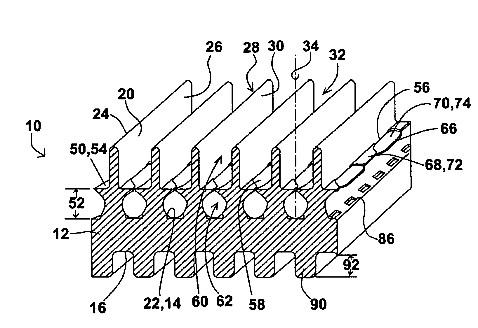
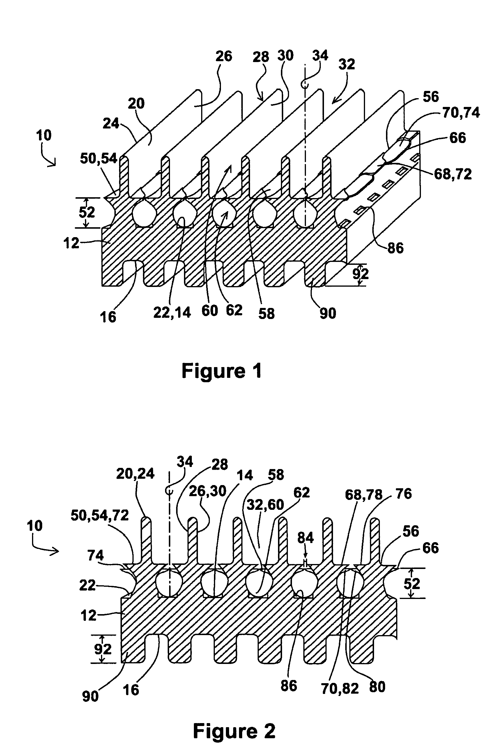
[0060]The dimensions of the current invention can vary, but example dimensions are provided below which will give the reader an idea as to at least one embodiment of the current invention.

[0061]The inter-fin distance is the distance between a center point of two adjacent fins 20 and this distance can be between 0.3 and 0.7 millimeters.

[0062]The fin 20 has a thickness above the wing 50 which is referred to as the fin thickness, and this thickness can be between 0.05 and 0.3 millimeters.

[0063]The fin 50 has a height measured from the fin base 22 to the fin top 24, where the fin top 24 would be measured at a peak 42 if the fin had depressions 36, and the fin height can be between 0.5 and 1.5 millimeters.

[0064]The wing 50 has a height 52 measured from the tube body outer surface 14 to the wing upper surface 54. The lower wing height 52 can be 0.15 to 0.5 millimeters, and the upper wing height 52 can be 0.2 to 0.6 millimeters, with the difference in wing height 52 between the upper and l...


PUM

PropertyMeasurementUnit
Areaaaaaaaaaaa
Areaaaaaaaaaaa
Condensation enthalpyaaaaaaaaaa

Abstract

A finned tube includes channels defined between adjacent fins on the tube body outer surface. Wings extend from side walls of the adjacent fins between the fin top and the fin base such that the wings form a barrier which splits the channel into an upper channel and a lower channel. A plurality of holes penetrate the barrier where the wings meet, so liquids and gases can pass into and out of the enclosed area defined by the lower channel. The wings can include alternating upper wings and lower wings, and there can be depressions formed in the fin top.

Description

BACKGROUND OF THE INVENTION[0001]1. Field of the Invention[0002]The current invention describes finned tubes used for heat transfer, such as the tubes used in shell and tube heat exchangers.[0003]2. Description of the Related Art[0004]Finned tubes have been used for heat transfer for many years. Heat flows from hot to cold, so heat transfer is accomplished by conducting heat from a warmer material to a cooler material. There is also heat given off when a material condenses from a vapor to a liquid, and heat is absorbed when a liquid vaporizes or evaporates from a liquid to a vapor. When finned tubes are used for heat transfer, the warmer material is on either the inside or the outside of the tube and the cooler material is on the other side. Usually the tube allows for the transfer of heat without mixing the warmer and cooler materials.[0005]For cooling purposes, a cooling medium can be a liquid such as cooling water flowing through a shell and tube heat exchanger, or it can be a ga...

Claims


Application Information

Patent Timeline
IPC IPC(8): F28F1/12B21D53/06
CPCF28F1/36F28F1/40F28F13/187Y10T29/49378
Inventor CAO, JIANYINGLUO, ZHONGWU, JIANQIU, YALIN
Owner WIELAND WERKE AG
Why Eureka
Try Eureka