
Rail Element For Conveying Suspended Objects, Preform-Supply Device Comprising One Such Element And Curved Flat Band Which Can Be Fixed To One Such Element

a technology for conveying objects and rail elements, which is applied in the direction of lighting and heating apparatus, furniture, charge manipulation, etc., can solve the problem of not being able to use a runner having a narrower width on the same frame, and achieve the effect of limiting the lateral swing of the conveyed objects and accelerating the flow of objects

Inactive Publication Date: 2008-08-21
SIDEL PARTICIPATIONS SAS
View PDF14 Cites 13 Cited by
  • Summary
  • Abstract
  • Description
  • Claims
  • Application Information

AI Technical Summary

Benefits of technology

[0039]To lock the runner in position and prevent its displacement while objects are being conveyed, the support means advantageously take the form of an offset provided in each branch of the conveying rail.
[0041]To fasten the runners removably to the frame and enable them to be replaced rapidly, at least one runner is fastened to the frame by way of screwing means.
[0043]To prevent the body part of the conveyed object being brought into contact with the frame, and possible jamming, the rail element according to the invention comprises means designed to limit the lateral swinging of the conveyed objects.
[0045]To prevent a longitudinal swinging movement, i.e. from front to rear, of the conveyed objects as they are being conveyed, the rail element comprises means designed to keep the conveyed objects bearing on the runners.
[0047]To improve the sliding behavior of the objects conveyed on the runners, these runners comprise a groove in which a sliding strip is mounted removably, in particular by snap-fitting.

Problems solved by technology

The fact is that if the support means were just complementary in shape with the runner, it would then not be possible to use a runner having a narrower width on the same frame.

Method used


Image

  • Rail Element For Conveying Suspended Objects, Preform-Supply Device Comprising One Such Element And Curved Flat Band Which Can Be Fixed To One Such Element
  • Rail Element For Conveying Suspended Objects, Preform-Supply Device Comprising One Such Element And Curved Flat Band Which Can Be Fixed To One Such Element
  • Rail Element For Conveying Suspended Objects, Preform-Supply Device Comprising One Such Element And Curved Flat Band Which Can Be Fixed To One Such Element

Examples


Embodiment Construction

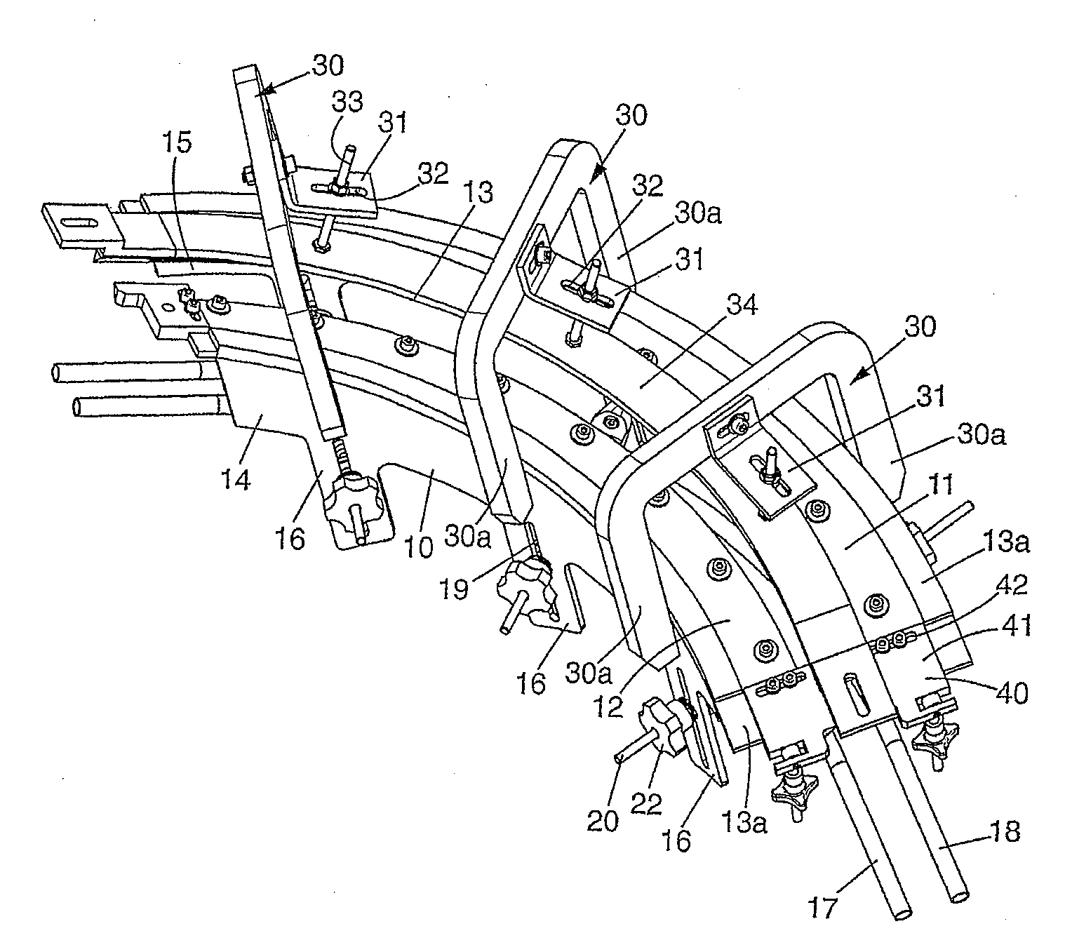
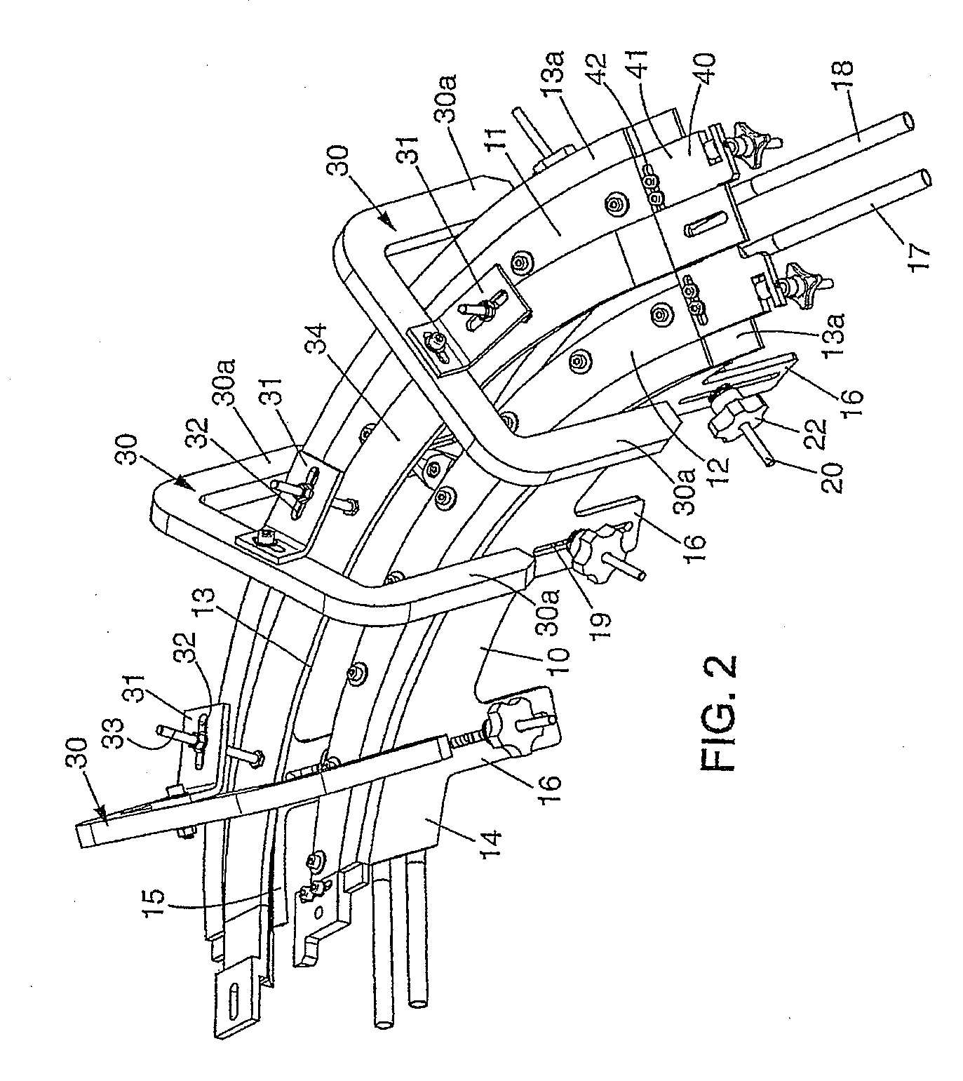
[0056]The conveying rail element according to the invention represented in FIG. 2 comprises a frame 10 supporting two removable runners 11, 12 which bound a conveying passageway 13 for objects suspended on these two runners 11, 12.

[0057]The runners 11, 12 form a conveying rail, for example a preform feed rail for a machine for blow-molding containers (this machine not being shown in the figures but being of a type which is known per se).

[0058]In the embodiment shown in the figures, this conveying operation is performed by gravity: the objects such as preforms or bottles are suspended on the runners 11, 12 and flow by gravity in the conveying passageway 13, the runners 11, 12 being curved in-plane and / or out-of-plane on the frame 10, so as to form a helical or helicoidal section.

[0059]However, it is intended that the invention can be used for conveying rails in which the conveyed objects are propelled by a fluid, for example air.

[0060]It is also intended that the invention can be use...


PUM

PropertyMeasurementUnit
shapeaaaaaaaaaa
distanceaaaaaaaaaa
massaaaaaaaaaa

Abstract

The invention relates to a rail element for conveying suspended objects, such as bottles or preforms. The inventive element comprises two guide rails (11, 12) which are separated by a pre-defined distance and which form lateral support surfaces for the objects being conveyed along a conveyor passageway (13), such as preform sub-neck guides. The invention is characterised in that it defines a helically-curved conveyor section and consists of a frame (10) on which the guide rails (11, 12) are helically arranged, whereby at least one guide rail (11, 12) comprises a flat band that can be removed from the frame (10).

Description

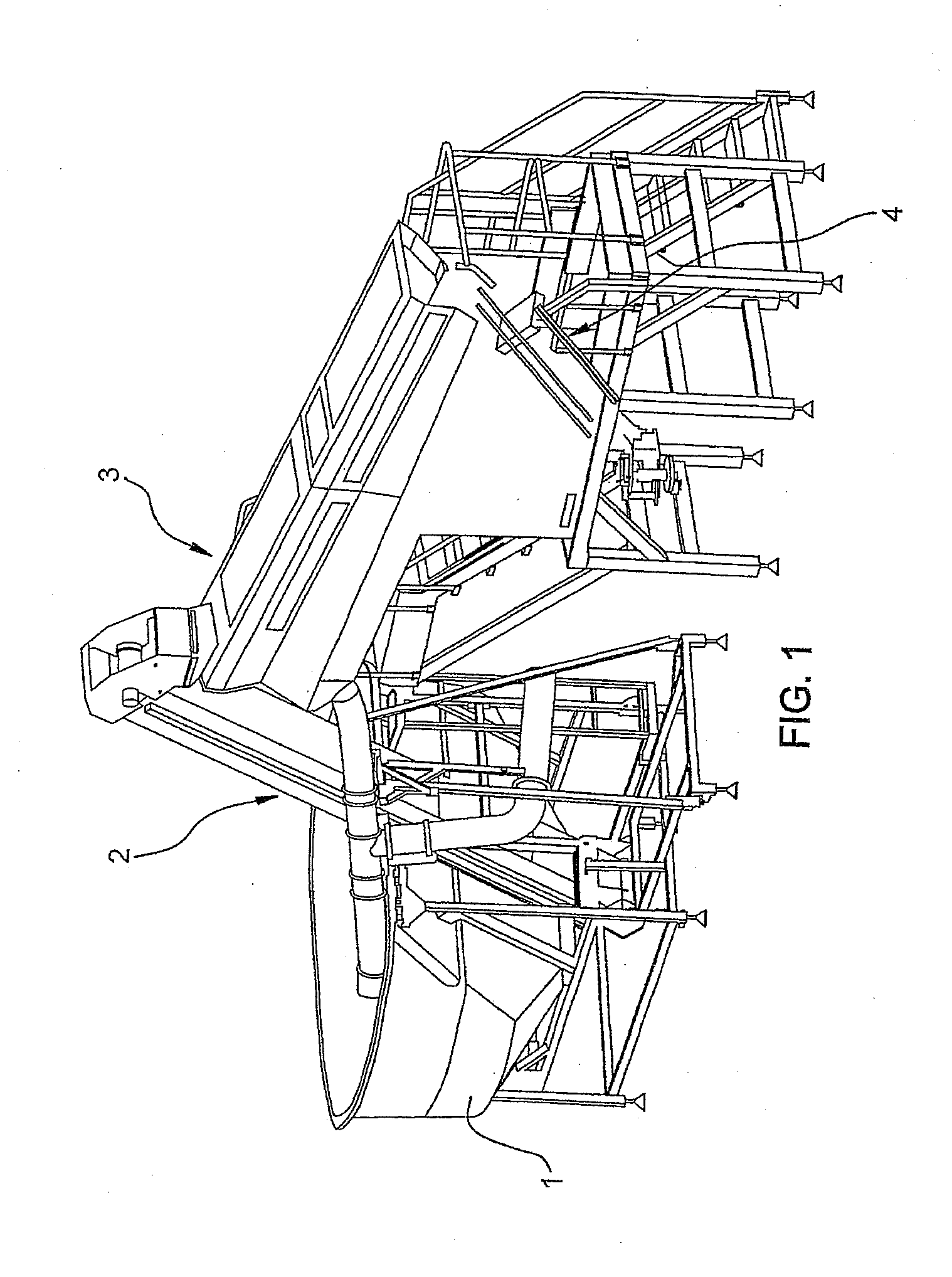
TECHNICAL FIELD[0001]The present invention relates to a rail element for conveying objects in a suspended position, a preform feed device comprising such an element, and a curved flat strip which can be fastened to such an element.[0002]Although intended more particularly for transporting preforms, the invention can be used for transporting bottles, jars or similar objects.BACKGROUND OF THE INVENTION[0003]The invention will be described more particularly within the context of its application to a container blow-molding apparatus in which the container is obtained by blow-molding a preform produced beforehand by injection molding. This preform has a substantially tubular body which is closed at one of its axial ends. Its other end has, right from this injection-molding operation, the final shape of the neck of the container.[0004]Generally, the neck of the container comprises a thread and, at its base, an annular support flange which extends radially outward.[0005]FIG. 1 of the appen...

Claims


Application Information

Patent Timeline
Patent Type & Authority Applications(United States)
IPC IPC(8): B65G49/05
CPCB65G51/035B29C49/4205B29C49/42057B29C49/42097
Inventor LEMAISTRE, ERICCHARPENTIER, ALAINSAVARY, CYRIL
Owner SIDEL PARTICIPATIONS SAS
Learn More