

Drinking Straw
- Summary
- Abstract
- Description
- Claims
- Application Information
AI Technical Summary
Benefits of technology
Problems solved by technology
Method used
Image

Examples
Embodiment Construction
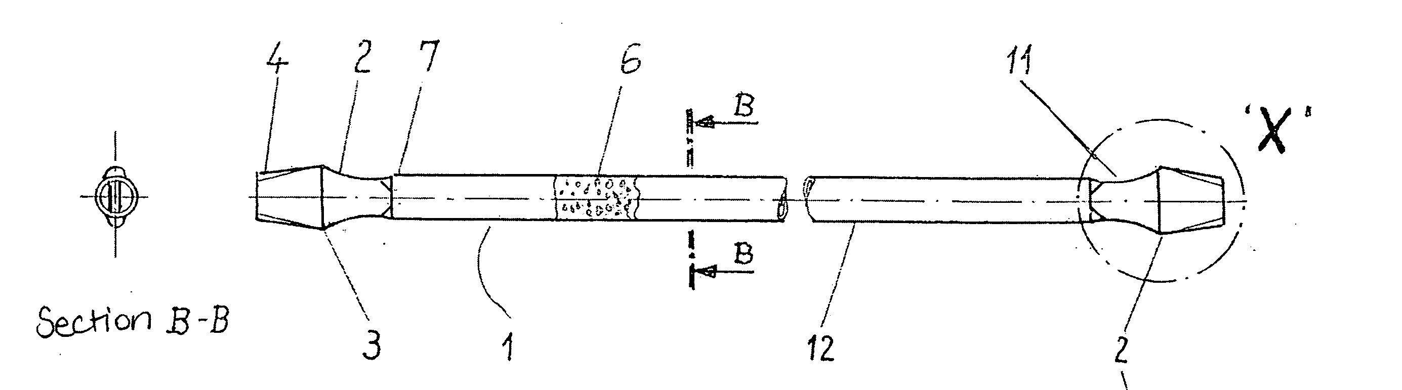
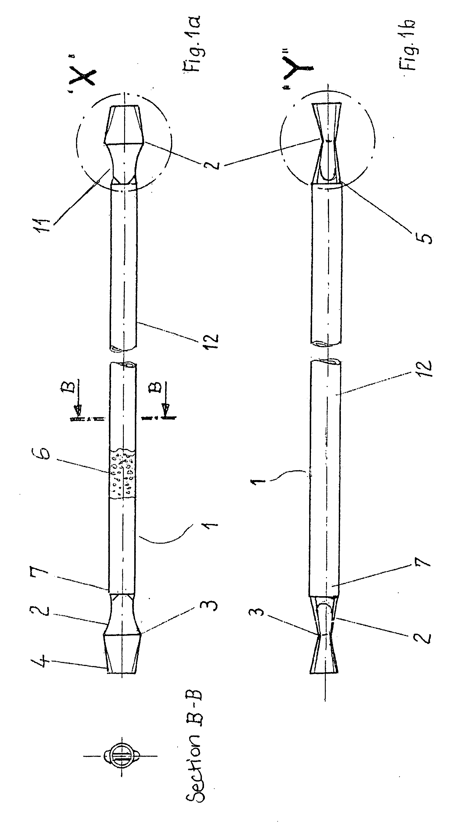
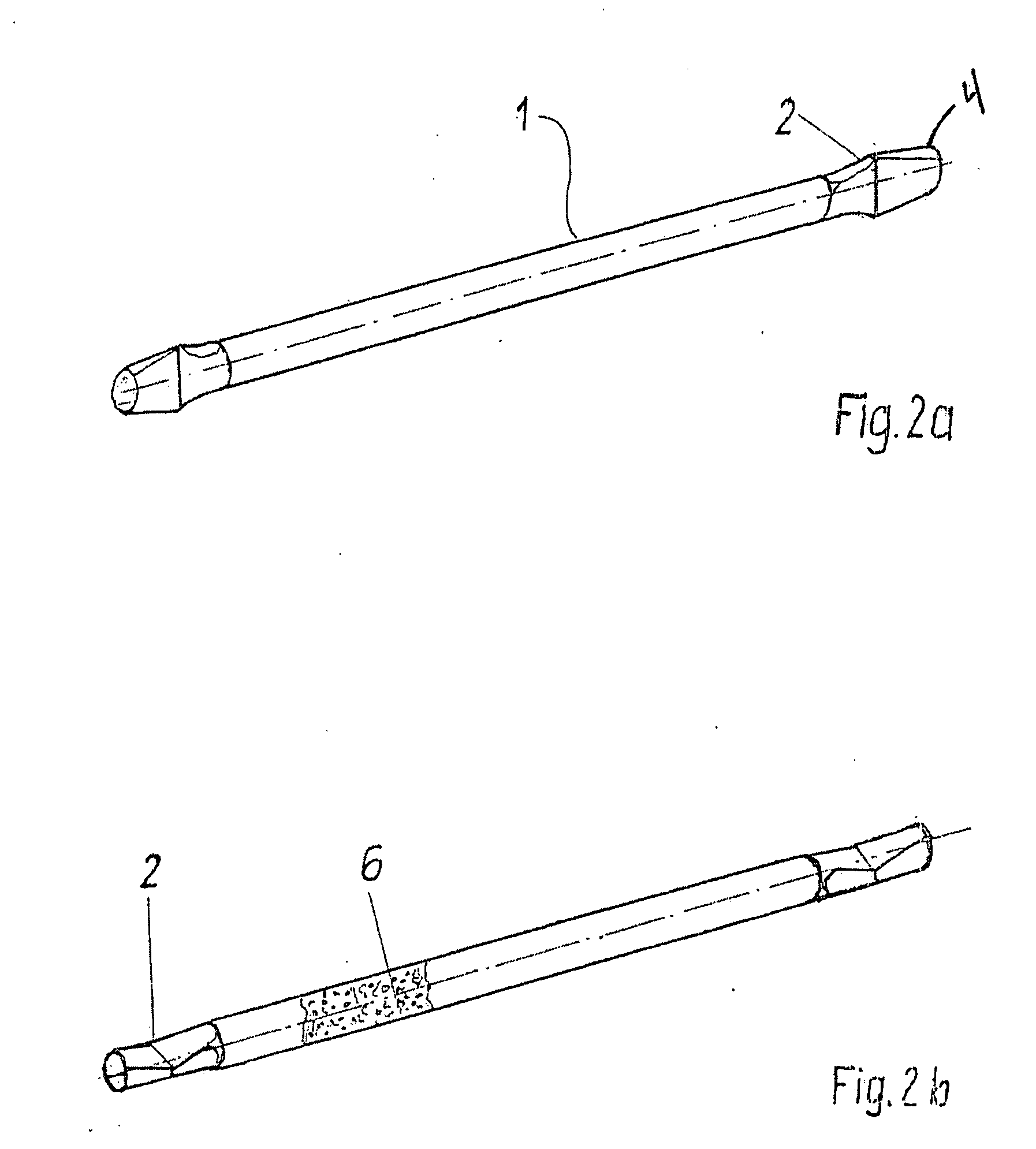
[0048]FIG. 1a shows the straw according to the present invention 1 in plan view and as a sectional view taken along the lines b-b. At the middle section 12 of the straw are located the two straw end ranges 7 and the aligned end-pieces 2. The end-piece 2 within the framed range consists of a cone area 11 tapering outwards which functions as a swirl mixing area and continues in a grooving 3. Beyond the grooving the straw material expands again and leads to the mouthpiece 4. The straw middle section 12 serves as a supply container for dry contents 6.
[0049]FIG. 1b illustrates an embodiment in accordance with the invention as shown in FIG. 1a in a longitudinal view and rotated 90°. In this figure the end-piece is presented with a tapering cone area 11 and an expanding mouthpiece 4. The closure 5 is located between end-piece 2 of the straw end 7 and the straw middle section 12. The closure 5 is intended to prevent the contents from falling out, as well as to ensure storage stability of th...
PUM
 Abstract
Description
Claims
Application Information