Zoom lens and image capture apparatus

a technology of zoom lens and image capture device, which is applied in the direction of mountings, optics, instruments, etc., can solve the problems of complicated construction of zoom barrel, and achieve the effect of high performance and compactness, and sufficient back focus

Active Publication Date: 2008-08-21
SONY CORP
View PDF3 Cites 10 Cited by
  • Summary
  • Abstract
  • Description
  • Claims
  • Application Information

AI Technical Summary

Benefits of technology

[0008]In view of the above and other issues, it is desirable to provide a zoom lens which is suitable for an interchangeable lens releasably attached to a silver-salt-film single-lens reflex camera or a digital single-lens reflex lens, being high-performance and compact and ensuring sufficient back focus, and an image capture apparatus using such a zoom lens.

Problems solved by technology

However, the zoom lens disclosed in Patent Literature 1 requires the six-group configuration, which in turn makes a zoom barrel construction complicated, whereas the zoom lens disclosed in Patent Literature 2 has an angle of view at the wide-angle end of approximately 75 degrees, which is insufficient.

Method used


Image

  • Zoom lens and image capture apparatus
  • Zoom lens and image capture apparatus
  • Zoom lens and image capture apparatus

Examples


first embodiment

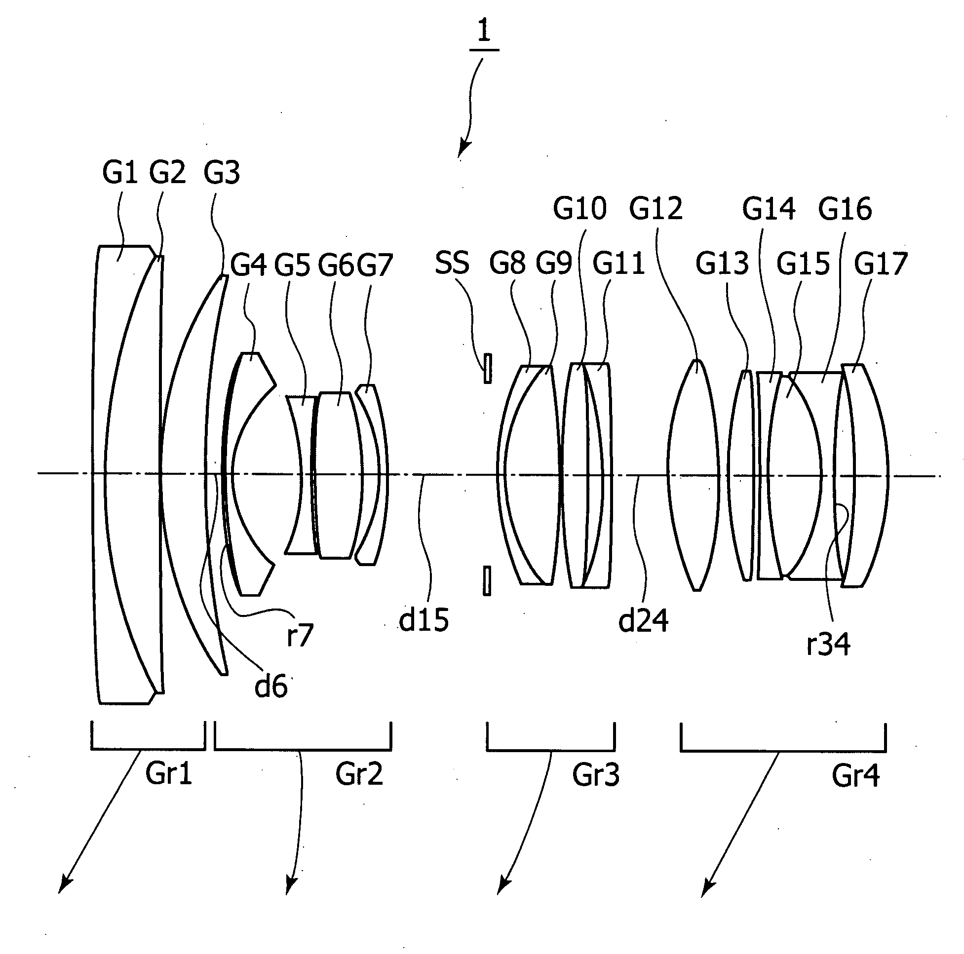
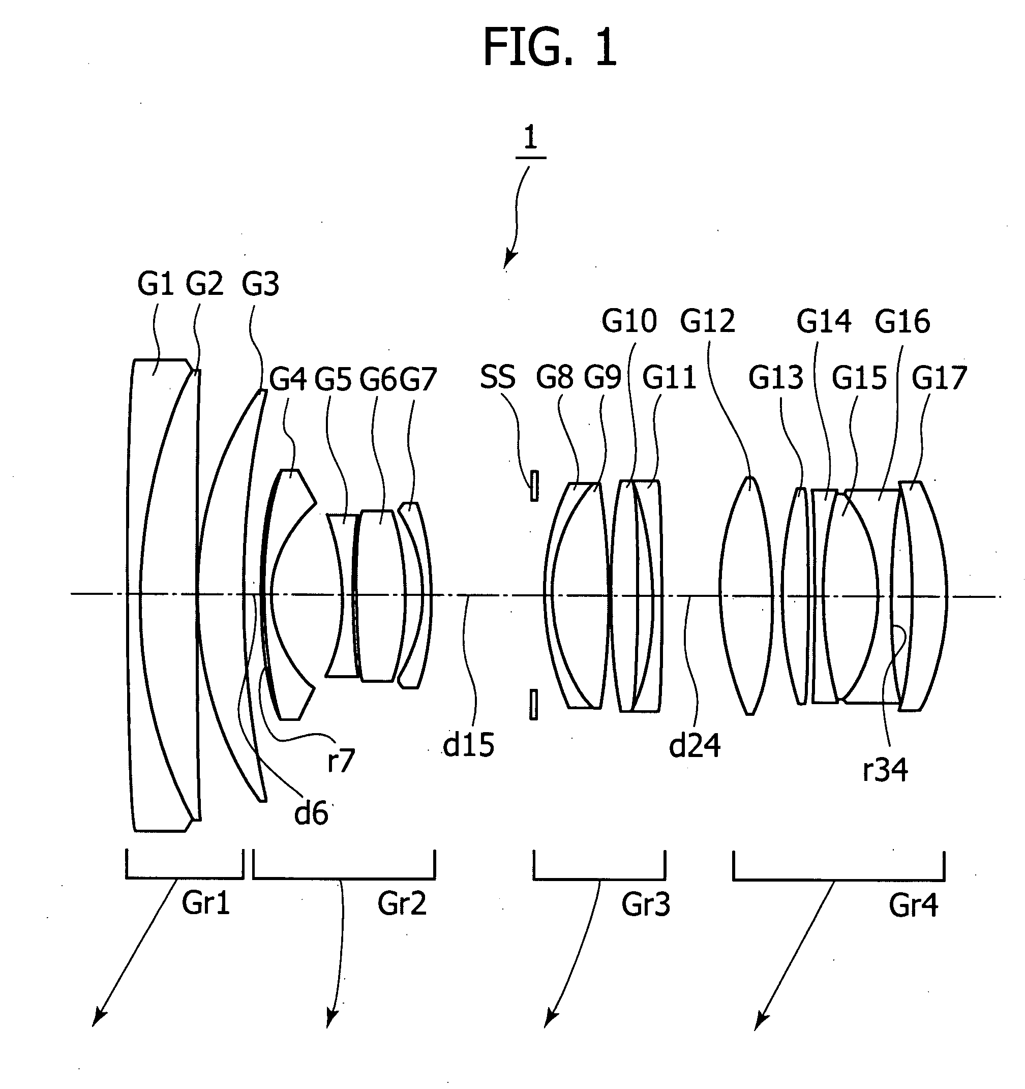
[0044]FIG. 1 shows the lens construction at the wide-angle end of a zoom lens 1 indicating, with arrows, motion loci of its constituent lens groups along the optical axis toward the telephoto end, respectively.

[0045]The zoom lens 1 includes, in the following order from the object side, a first lens group Gr1 having positive refractive power, a second lens group Gr2 having negative refractive power, a third lens group Gr3 having positive refractive power, and a fourth lens group Gr4 having positive refractive power. During zooming from the wide-angle end to the telephoto end, the first to fourth lens groups move toward the object side as indicated by the arrows, respectively, in FIG. 1 such that the distance between the first lens group Gr1 and the second lens group Gr2 increases, the distance between the second lens group Gr2 and the third lens group Gr3 decreases, and the distance between the third lens group Gr3 and the fourth lens group Gr4 decreases. Further, the second lens gr...

second embodiment

[0052]FIG. 5 shows the lens construction at a wide-angle end of a zoom lens 2 indicating, with arrows, motion loci of its constituent lens groups along the optical axis toward a telephoto end, respectively.

[0053]The zoom lens 2 includes, in the following order from the object side, a first lens group Gr1 having positive refractive power; a second lens group Gr2 having negative refractive power; a third lens group Gr3 having positive refractive power; and a fourth lens group Gr4 having positive refractive power. During zooming from the wide-angle end to the telephoto end, the first to fourth lens groups move toward the object side as indicated by the arrows, respectively, in FIG. 5 such that a distance between the first lens group Gr1 and the second lens group Gr2 increases, a distance between the second lens group Gr2 and the third lens group Gr3 decreases, and a distance between the third lens group Gr3 and the fourth lens group Gr4 decreases. Further, the second lens group Gr2 mo...

third embodiment

[0060]FIG. 9 shows the lens construction at a wide-angle end of a zoom lens 3 indicating, with arrows, motion loci of its constituent lens groups along the optical axis toward a telephoto end, respectively.

[0061]The zoom lens 3 includes, in the following order from the object side, a first lens group Gr1 having positive refractive power; a second lens group Gr2 having negative refractive power; a third lens group Gr3 having positive refractive power; and a fourth lens group Gr4 having positive refractive power. During zooming from the wide-angle end to the telephoto end, the first to fourth lens groups move toward the object side as indicated by the arrows, respectively, in FIG. 9 such that a distance between the first lens group Gr1 and the second lens group Gr2 increases, a distance between the second lens group Gr2 and the third lens group Gr3 decreases, and a distance between the third lens group Gr3 and the fourth lens group Gr4 decreases. Further, the second lens group Gr2 mo...


PUM


Abstract

There is provided a zoom lens which includes, in an order from an object side, a first lens group having positive refractive power; a second lens group having negative refractive power; a third lens group having positive refractive power; and a fourth lens group having positive refractive power, and in which, during power variation from a wide-angle end to a telephoto end, a distance between the first lens group and the second lens group increases, a distance between the second lens group and the third lens group decreases, and a distance between the third lens group and the fourth lens group decreases, and the zoom lens includes at least one cemented-triplet lens block having negative refractive power, in the fourth lens group.

Description

BACKGROUND OF THE INVENTION[0001]1. Field of the Invention[0002]The present invention relates to a zoom lens and an image capture apparatus, and particularly to a zoom lens which is suitable for an interchangeable lens releasably attached to a silver-salt-film single-lens reflex camera or a digital single-lens reflex camera, being high-performance and ensuring sufficient lens back, and to an image capture apparatus using such a zoom lens.[0003]2. Description of Related Art[0004]In recent years, as the number of pixels in photoelectric conversion devices increases, there are demands for higher-performance image-taking optical systems, and moreover, for zoom lenses with small F-numbers covering a wide-angle range. In addition, in interchangeable lenses, there is a restriction that sufficient lens back be ensured, and this leads to difficulties in, e.g., correcting distortion associated with their wider-angle implementations.[0005]In a related art, e.g., Japanese Patent Application Pub...

Claims


Application Information

Patent Timeline
Patent Type & Authority Applications(United States)
IPC IPC(8): G02B15/16
CPCG02B15/161G02B7/282G02B15/142G02B15/144113
Inventor ARIMOTO, TETSUYAYAMAMOTO, YASUSHI
Owner SONY CORP
Why Eureka
Try Eureka