Camera lens

A camera lens and lens technology, which is applied in the field of camera lenses, can solve problems such as poor compensation of dispersion and chromatic aberration, short optical system, and full-length constraints, so as to improve resolution and image quality, and improve resolution and image quality , the effect of compensating dispersion and distortion chromatic aberration

Inactive Publication Date: 2004-07-28
ENPLAS CORP
View PDF0 Cites 4 Cited by
  • Summary
  • Abstract
  • Description
  • Claims
  • Application Information

AI Technical Summary

Problems solved by technology

[0005] However, in order to achieve compactness and light weight, since the overall length (dimension along the optical axis) of the optical system incorporated into the camera is significantly restricted, the lens must adopt a simple structure
When adopting the simplest structure, that is, a single spherical lens with only one lens structure, although the overall length of the optical system can meet the conditions, the dispersion and chromatic aberration cannot be well compensated, resulting in insufficient Problems with high resolution (such as 640×480 dots)
[0006] In addition, although a lens with a two-lens structure has been proposed, it is not perfect because it cannot meet the resolution requirements while satisfying the requirements for the overall length of the optical system.
[0007] On the other hand, if a lens with a structure of more than three lenses is used, although it can meet the resolution requirements, it cannot meet the constraints on the overall length of the optical system.
[0008] Thus, until now, in terms of how to solve the problem of obtaining a sufficiently high resolution while keeping the overall length of the optical system short, the actual situation is that no effective optical system has been proposed.

Method used


Image

  • Camera lens
  • Camera lens
  • Camera lens

Examples


specific Embodiment

[0071] Below, refer to Figure 2 to Figure 13 Examples of the present invention will be described.

[0072] Here, in this embodiment, f is the focal length of the entire lens, and f 1 is the focal length of the first lens 3, f 2 is the focal length of the second lens 4, and FNO represents the F number. In addition, ω is the half angle of view, its double 2ω is the full angle of view (diagonal angle of view), r is the radius of curvature of the optical system (in the case of a lens, it is the central radius of curvature), and d is the radius of curvature of the optical system. Thickness or air gap, ne is the refractive index of each optical system when irradiated with e-line (green), and νd is the Abbe number of each optical system when irradiated with d-line (yellow).

[0073] k, A, B, and C represent coefficients in the following formula (7). That is, the aspheric shape of the lens is the Z axis in the direction of the optical axis, the Y axis is the direction perpendicul...

no. 1 Embodiment

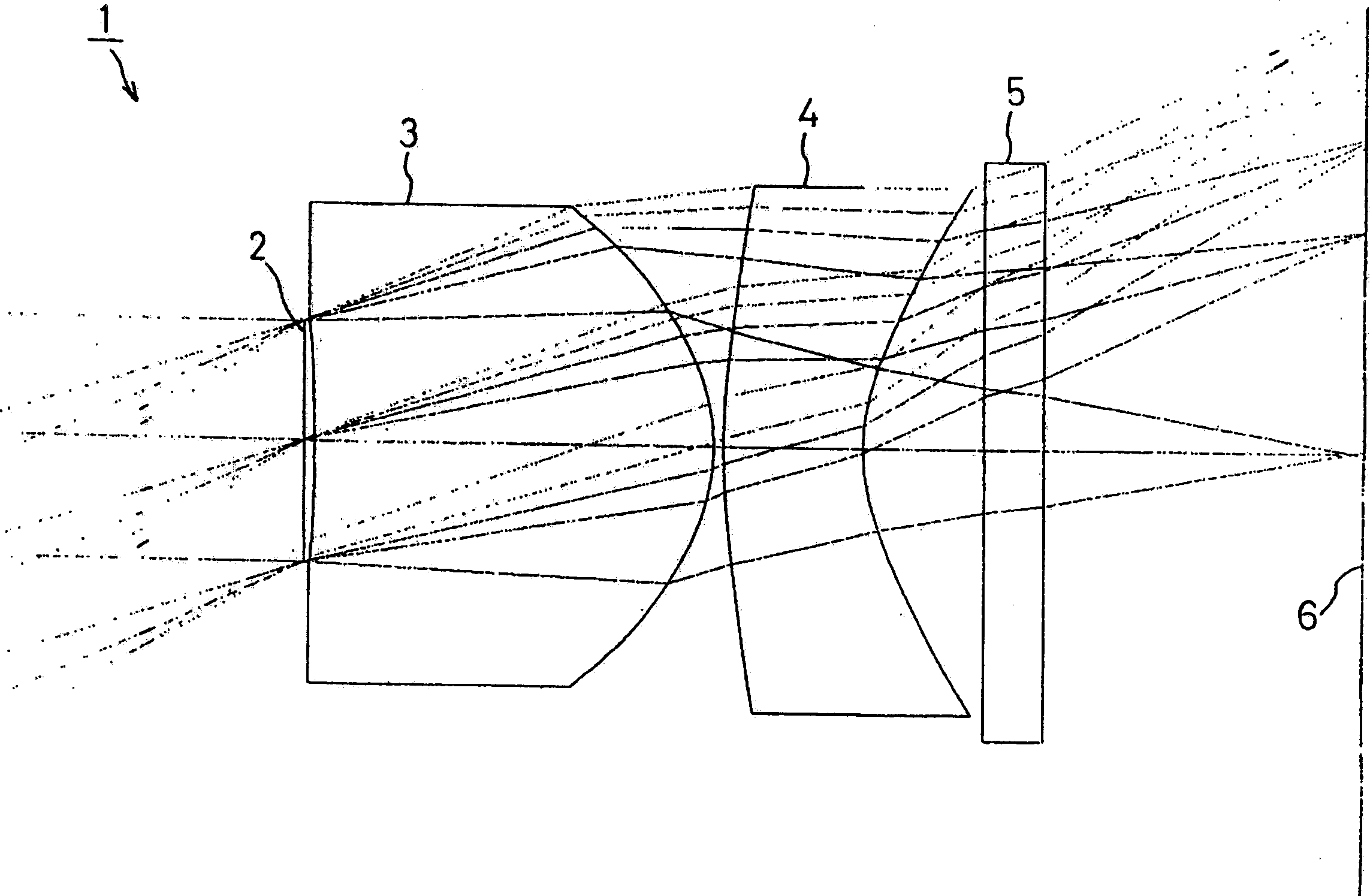
[0077] figure 2 Shown is the first embodiment of the present invention, in this embodiment, with figure 1 The imaging lens 1 with the structure shown is similarly provided with a diaphragm 2 on the object side of the first lens 3 and a cover glass 5 on the imaging surface 6 side of the second lens 4 .

[0078] The following conditions are set for the imaging lens 1 of the first embodiment.

[0079] f=3.40mm, FNO=2.8, 2ω=67.5°, f 1 =1.81mm, f 2 =-2.48mm

[0080] Surface Radius of curvature r Distance between surfaces d Refractive index ne Abbe number νd

[0081] (object point) ∞

[0082] (stop) 0.05

[0083] 1 (1st lens surface 1) -14.728 2.00 1.52692 56.2

[0084] 2 (1st lens 2nd surface) -0.936 0.05

[0085] 3 (2nd lens 1st surface) 3.417 0.70 1.58961 30.0

[0086] 4 (second lens surface 2) 0.945 0.60

[0087] 5 (1st side of cover glass) 0 0.30 1.51825 64.2

[0088] 6 (2nd side of cover glass) 0 1.575

[0089] (imaging surface)

[0090] Face k A B C

[0091] 1 ...

no. 2 Embodiment

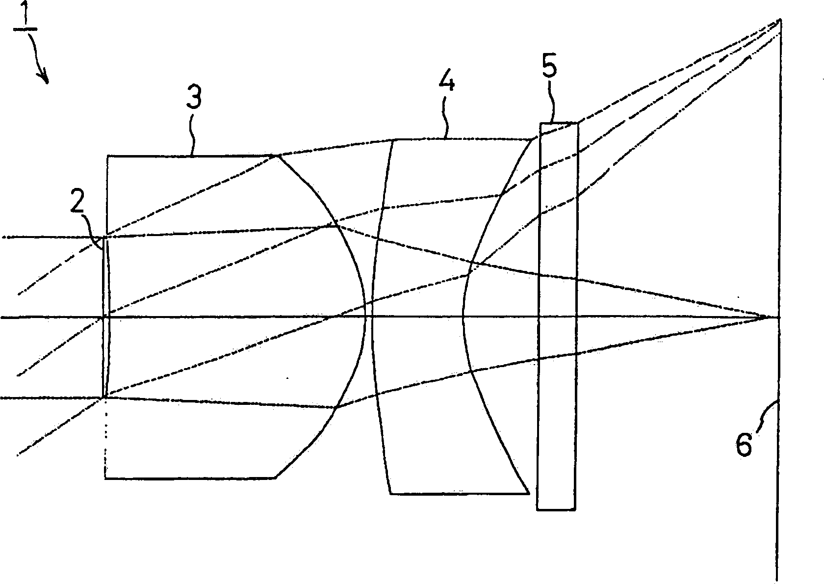
[0101] Figure 5 Shown is the second embodiment of the present invention, in this embodiment, with figure 1The imaging lens 1 with the structure shown is similarly provided with a diaphragm 2 on the object side of the first lens 3 and a cover glass 5 on the imaging surface 6 side of the second lens 4 .

[0102] The following conditions are set for the imaging lens 1 in the second embodiment.

[0103] f=3.40mm, FNO=2.8, 2ω=66.2°, f 1 =1.84mm, f 2 =-2.46mm

[0104] Surface Radius of curvature r Distance between surfaces d Color refractive index ne Abbe number νd

[0105] (object point) ∞

[0106] (stop) 0.05

[0107] 1 (1st lens surface 1) -25.266 2.00 1.49405 57.0

[0108] 2 (1st lens 2nd surface) -0.899 0.05

[0109] 3 (2nd lens 1st surface) 3.105 0.70 1.58961 30.0

[0110] 4 (second lens surface 2) 0.905 0.60

[0111] 5 (1st side of cover glass) 0 0.30 1.51825 64.2

[0112] 6 (2nd side of cover glass) 0 1.499

[0113] (imaging surface)

[0114] Face k A B C

[0...


PUM


Abstract

An imaging lens system includes, in the named order from the side of an object toward an image surface, a light amount diaphragm, a first lens having a positive power with a main power on the side closer to the image surface, a meniscus-shaped second lens having a negative power with a strong concave surface turned toward the image surface. Thus, it is possible to provide the imaging lens system in which a sufficiently high resolution can be obtained, while meeting the demand for a reduction in entire length of an optical system to provide the compactness.

Description

technical field [0001] The present invention relates to an imaging lens, and particularly relates to an imaging lens used in an imaging device using an imaging element such as a CCD or a CMOS. Background technique [0002] In recent years, the development of multimedia has been remarkable. For example, the demand for cameras using solid-state imaging elements such as CCD and CMOS, such as CCD cameras, mounted on mobile phones and the like has increased remarkably. Since such a CCD camera must be installed in a limited installation space, it is desired to be small in size and light in weight. Therefore, it is also required that an imaging lens for such a CCD camera be small in size and light in weight. [0003] As such an imaging lens, various optical systems have been proposed according to the application, and an optical system for the purpose of compactness and light weight has also been proposed for the camera mounted in the above-mentioned mobile phone. [0004] In rece...

Claims


Application Information

Patent Timeline
Patent Type & Authority Applications(China)
IPC IPC(8): G02B9/10G02B13/00G02B13/18
CPCG02B13/18G02B13/003G02B9/10
Inventor 金子勇
Owner ENPLAS CORP
Why Eureka
Try Eureka