Objective optical system for endoscope

An optical system and objective lens technology, which is applied in the field of endoscope objective lens optical system, can solve the problem that the position of the object is not included, and achieve the effect of short overall length and good correction of various aberrations

Active Publication Date: 2022-04-05
OLYMPUS CORP
View PDF2 Cites 0 Cited by
  • Summary
  • Abstract
  • Description
  • Claims
  • Application Information

AI Technical Summary

Problems solved by technology

In addition, the object position during magnified observation is not included in the depth of field of the objective optical system during normal observation

Method used


Image

  • Objective optical system for endoscope
  • Objective optical system for endoscope
  • Objective optical system for endoscope

Examples


Embodiment 1

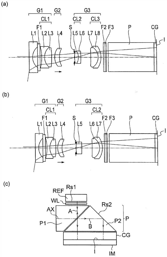
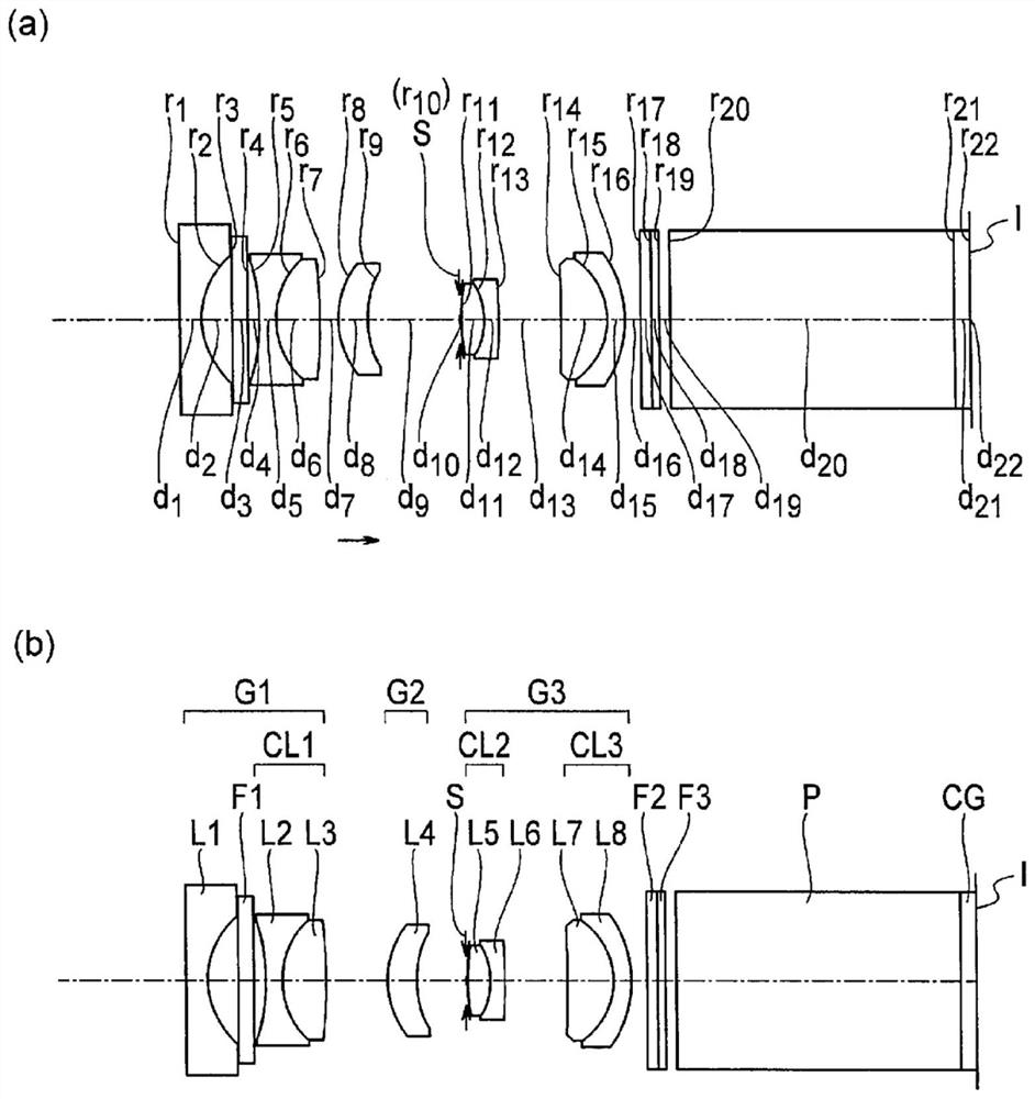
[0152] The objective optical system for an endoscope according to Example 1 will be described. The objective optical system for an endoscope of Embodiment 1 includes a first lens group G1 having a negative refractive power, a second lens group G2 having a positive refractive power, and a third lens group G2 having a positive refractive power, which are sequentially arranged from the object side to the image side. Lens group G3.

[0153] The first lens group G1 has a plano-concave negative lens L1 whose object side is a plane, a bi-concave negative lens L2, and a bi-convex positive lens L3. Here, a cemented lens CL1 is formed by a biconcave negative lens L2 and a biconvex positive lens L3.

[0154] The second lens group G2 has a positive meniscus lens L4 with a convex surface facing the object side.

[0155] The third lens group G3 has a biconvex positive lens L5, a negative meniscus lens L6 having a convex surface facing the image side, a biconvex positive lens L7, and a neg...

Embodiment 2

[0161] The objective optical system for an endoscope according to Example 2 will be described. The objective optical system for an endoscope of Embodiment 2 includes a first lens group G1 having a negative refractive power, a second lens group G2 having a positive refractive power, and a third lens group G2 having a positive refractive power, which are sequentially arranged from the object side to the image side. Lens group G3.

[0162] The first lens group G1 has a plano-concave negative lens L1 whose object side is a plane, a bi-concave negative lens L2, and a bi-convex positive lens L3. Here, a cemented lens CL1 is formed by a biconcave negative lens L2 and a biconvex positive lens L3.

[0163] The second lens group G2 has a positive meniscus lens L4 with a convex surface facing the object side.

[0164] The third lens group G3 has a biconvex positive lens L5, a negative meniscus lens L6 having a convex surface facing the image side, a biconvex positive lens L7, and a neg...

Embodiment 3

[0170] The objective optical system for an endoscope according to Example 3 will be described. The objective optical system for an endoscope of Embodiment 3 includes a first lens group G1 having a negative refractive power, a second lens group G2 having a positive refractive power, and a third lens group G2 having a positive refractive power, which are sequentially arranged from the object side to the image side. Lens group G3.

[0171] The first lens group G1 has a plano-concave negative lens L1 whose object side is a plane, a bi-concave negative lens L2, and a bi-convex positive lens L3. Here, a cemented lens CL1 is formed by a biconcave negative lens L2 and a biconvex positive lens L3.

[0172] The second lens group G2 has a positive meniscus lens L4 with a convex surface facing the object side.

[0173] The third lens group G3 has a biconvex positive lens L5, a negative meniscus lens L6 having a convex surface facing the image side, a positive meniscus lens L7 having a c...


PUM


Abstract

To provide an objective optical system for an endoscope that has a sufficient back focus, has a short overall length of the optical system, and corrects various aberrations well. The objective optical system for an endoscope is equipped with a first lens group (G1) having a negative refractive power, a second lens group (G2) and a third lens group (G3) having a positive refractive power arranged in order from the object side to the image side , when focusing, the second lens group (G2) moves along the direction of the optical axis, and the third lens group (G3) has a front group and a rear group arranged from the object side to the image side, and the front group is composed of a positive refractive power cemented lens , or consist of a single lens with positive refractive power, and the rear group is composed of a cemented lens with positive refractive power, satisfying the following conditional formula (1). 0.45

Description

technical field [0001] The invention relates to an objective lens optical system for an endoscope. Background technique [0002] In a medical endoscope, magnified observation is used for observation of a lesion. In order to zoom in and observe the lesion, it is necessary to find the lesion. In magnified observation, the observation range is narrower than conventional observation (hereinafter referred to as "normal observation"). Therefore, it is not easy to find the lesion by magnified observation. Under such circumstances, it is desirable to be able to perform normal observation and magnified observation with one objective optical system. [0003] In magnified observation, the distance from the objective optical system to the position of the object (hereinafter referred to as "object distance") is, for example, about 3 mm. On the other hand, in normal observation, the object distance is much longer than 3 mm. [0004] When the optical system is configured such that the...

Claims


Application Information

Patent Timeline
Patent Type & Authority Patents(China)
IPC IPC(8): G02B13/04
CPCG02B9/60A61B1/00188G02B23/243G02B7/04A61B1/00096A61B1/05G02B9/12G02B13/04A61B1/04A61B1/00163
Inventor 中村稔
Owner OLYMPUS CORP
Why Eureka
Try Eureka