

Imaging lens
a technology of imaging lens and lens body, applied in the field of imaging lens, can solve the problems of insufficient wide angle of view, structurally impossible to apply this imaging lens, difficult resin filling work, etc., and achieve the effect of shortening the distance between the lens and the total track length, adequate back focus, and shortening the total track length
- Summary
- Abstract
- Description
- Claims
- Application Information
AI Technical Summary
Benefits of technology
Problems solved by technology
Method used
Image

Examples
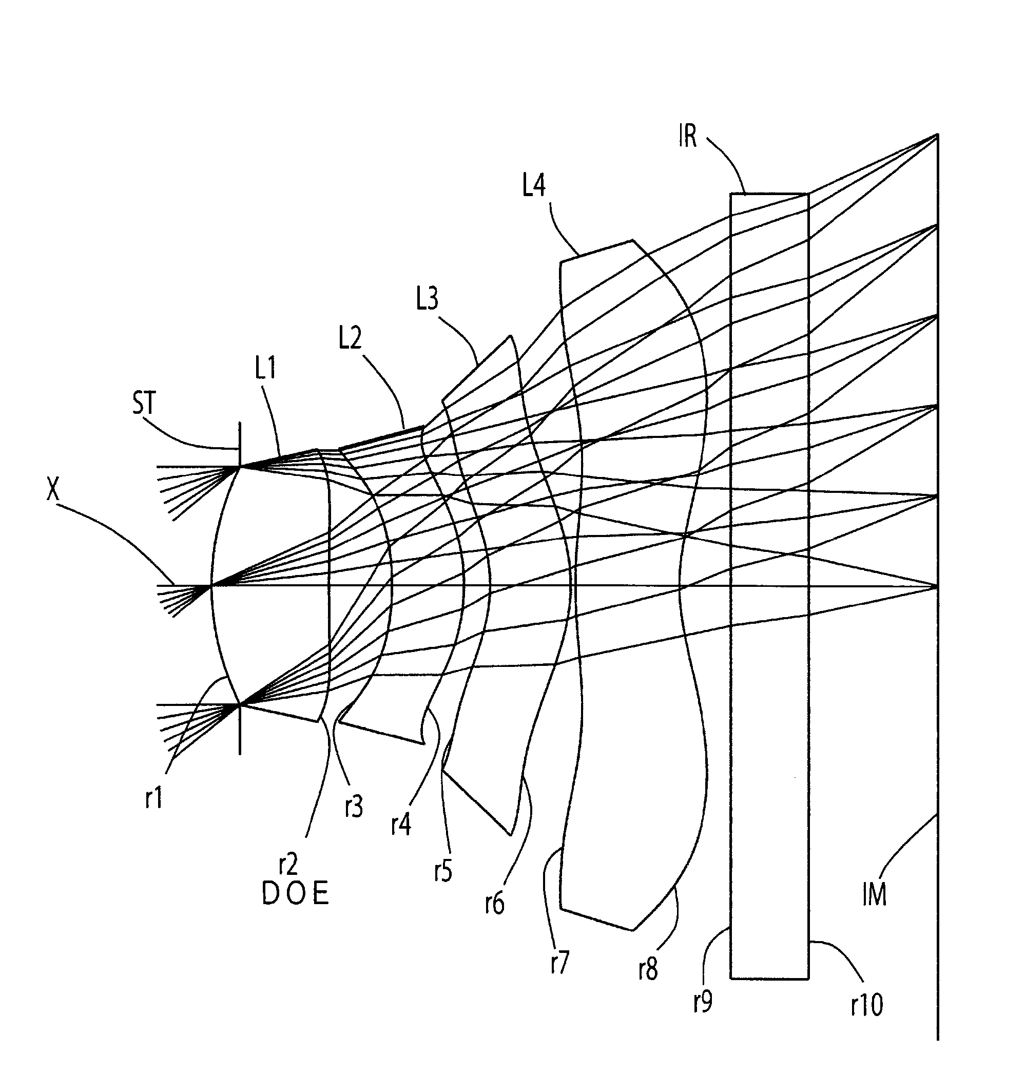
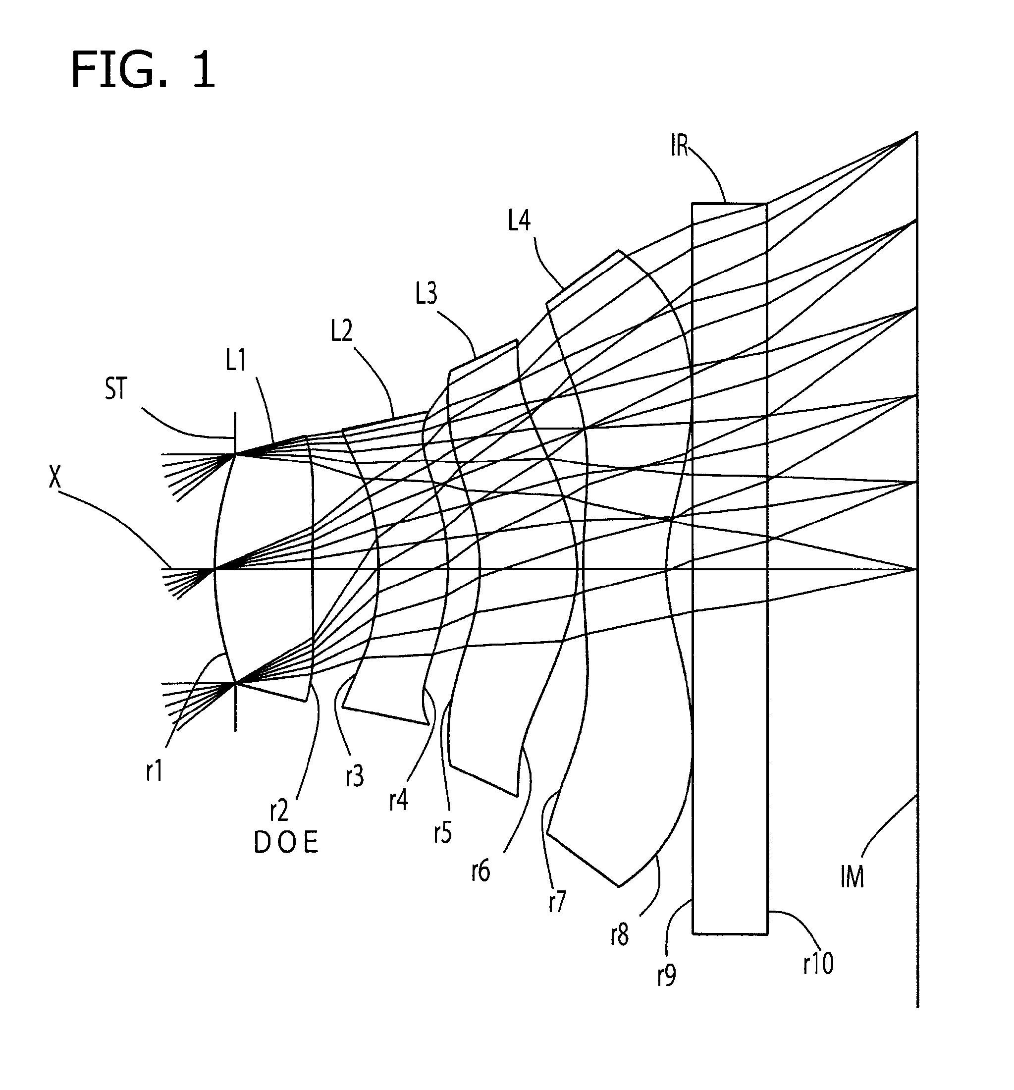
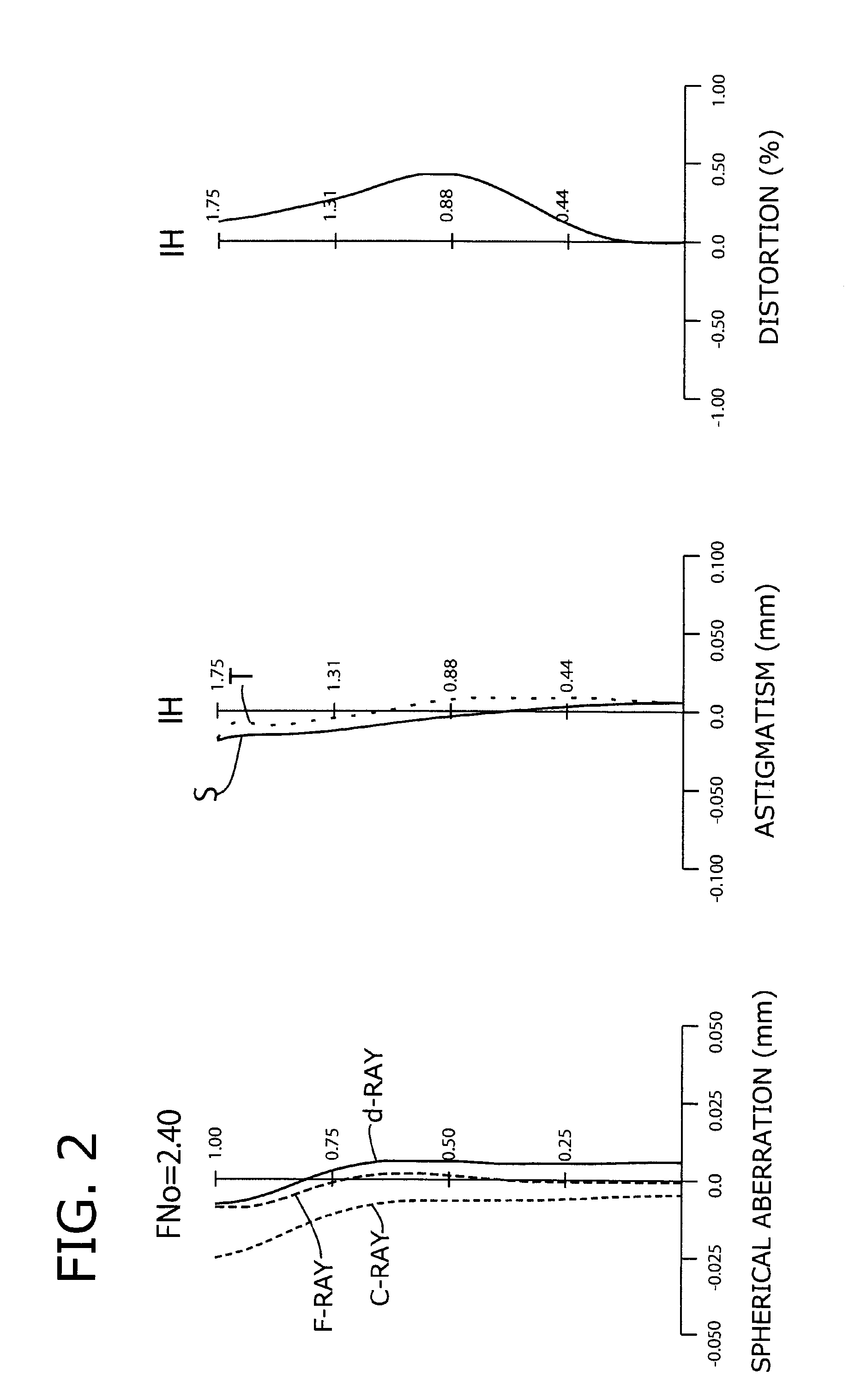
embodiment 1
[0091]The basic lens data of Embodiment 1 is shown below in Table 1.
TABLE 1Embodiment 1Unit mmf = 2.176Fno = 2.40ω(°) = 38.81IH = 1.75Surface DataCurvatureSurfaceRefractive IndexAbbe No.Surface No. iRedius rdistance dNdvd(Object Surface)InfinityInfinity 1* (Stop)1.1980.3941.614225.58 2* (DOE)7.2960.266 3*−1.1940.2801.534656.16 4*−0.9330.128 5*−0.7460.3941.534656.16 6*−0.6330.024 7*2.2820.3351.534656.16 8*0.7220.300 9*Infinity0.3001.516864.2010*Infinity0.415Image planeInfinitySingle lens dataLensStart planeFocal Length111.985235.785353.52647−2.127Aspheric data1st Surface2nd Surface3rd Surface4th Surfacek−3.376E+00−9.800E+01−5.653E−01−1.317E−01A41.634E−01−3.131E−01−9.108E−01−9.159E−02A6−7.042E−01−1.194E+009.538E−012.478E+00A81.577E+001.162E+009.959E+004.983E+00A10−6.121E+00−7.521E−01−1.705E+01−1.166E+01A120.000E+000.000E+000.000E+003.697E+00A140.000E+000.000E+000.000E+000.000E+00A160.000E+000.000E+000.000E+000.000E+005th Surface6th Surface7th Surface8th Surfacek−1.163E+00−4.503E+000.0...
embodiment 2
[0095]The basic lens data of Embodiment 2 is shown below in Table 2.
TABLE 2Embodiment 2Unit mmf = 2.167Fno = 2.38ω(°) = 38.88IH = 1.75Surface DataCurvatureSurfaceRefractive IndexAbbe No.Surface No. iRedius rdistance dNdvd(Object Surface)InfinityInfinity 1* (Stop)0.9890.4561.534656.16 2* (DOE)5.5120.246 3*−1.0610.2801.534656.16 4*−0.7740.101 5*−0.6120.3141.614225.58 6*−0.6640.020 7*1.8550.4041.534656.16 8*0.7760.107 9*Infinity0.3001.516864.2010*Infinity0.600Image planeInfinitySingle lens dataLensStart planeFocal Length111.992233.985359.66447−2.859Aspheric data1st Surface2nd Surface3rd Surface4th Surfacek−1.184E+01−2.445E+01−6.039E−011.877E−01A41.447E+00−5.997E−01−1.510E+00−7.187E−01A6−6.013E+001.261E+00−1.537E+005.469E+00A81.935E+01−1.316E+011.962E+01−1.326E+00A10−3.308E+011.709E+01−2.490E+01−3.528E+00A120.000E+000.000E+000.000E+001.116E+01A140.000E+000.000E+000.000E+000.000E+00A160.000E+000.000E+000.000E+000.000E+005th Surface6th Surface7th Surface8th Surfacek−1.147E+00−2.982E+000.0...
embodiment 3
[0099]The basic lens data of Embodiment 3 is shown below in Table 3.
TABLE 3Embodiment 3Unit mmf = 2.197Fno = 2.41ω(°) = 38.58IH = 1.75Surface DataCurvatureSurfaceRefractive IndexAbbe No.Surface No. iRedius rdistance dNdvd(Object Surface)InfinityInfinity 1* (Stop)1.1950.3931.614225.58 2* (DOE)7.2060.273 3*−1.1920.2841.534656.16 4*−0.9670.115 5*−0.8080.4041.534656.16 6*−0.6380.021 7*2.2610.3271.534656.16 8*0.6930.200 9*Infinity0.3001.516864.2010*Infinity0.538Image planeInfinitySingle lens dataLensStart planeFocal Length112.000236.624353.08447−2.009Aspheric data1st Surface2nd Surface3rd Surface4th Surfacek−3.294E+00−9.196E+01−7.717E−01−8.775E−02A41.637E−01−3.026E−01−8.903E−01−8.448E−02A6−7.110E−01−1.098E+008.907E−012.410E+00A81.836E+001.236E+009.771E+004.711E+00A10−6.696E+00−2.260E+00−1.853E+01−1.195E+01A120.000E+000.000E+000.000E+004.572E+00A140.000E+000.000E+000.000E+000.000E+00A160.000E+000.000E+000.000E+000.000E+005th Surface6th Surface7th Surface8th Surfacek−1.036E+00−4.803E+000.0...
PUM
 Abstract
Description
Claims
Application Information