
Method of examining irregular defects of dental implant

a dental implant and irregular defect technology, applied in the field of examining irregular defects of dental implants, can solve the problems of insufficient clinical examination of the implant on a 2-dimensional x-ray image film, insufficient diagnosis of irregular bone defects, and prior arts that do not fulfill all users' requests on actual use, etc., to achieve the effect of improving the surgical efficiency of dental implants

Inactive Publication Date: 2008-08-21
NAT CENT UNIV
View PDF1 Cites 10 Cited by
  • Summary
  • Abstract
  • Description
  • Claims
  • Application Information

AI Technical Summary

Benefits of technology

[0008]The third purpose of the present invention is to obtain more information than by clinical examination based on a 2-dimensional X-ray image film or by measuring resonance frequency of the implant for obtaining stability of the whole structure only.
[0009]The fourth purpose of the present invention is to reliably diagnose an implant osseointegration to improve surgeries of dental implant in a rate of success; and to make the diagnosis applicable to implants other than dental implant.
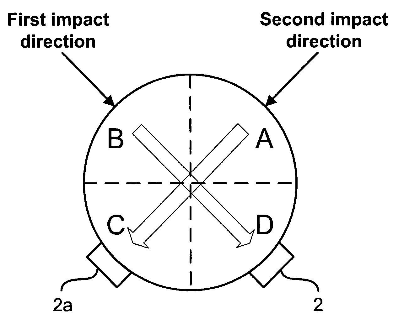
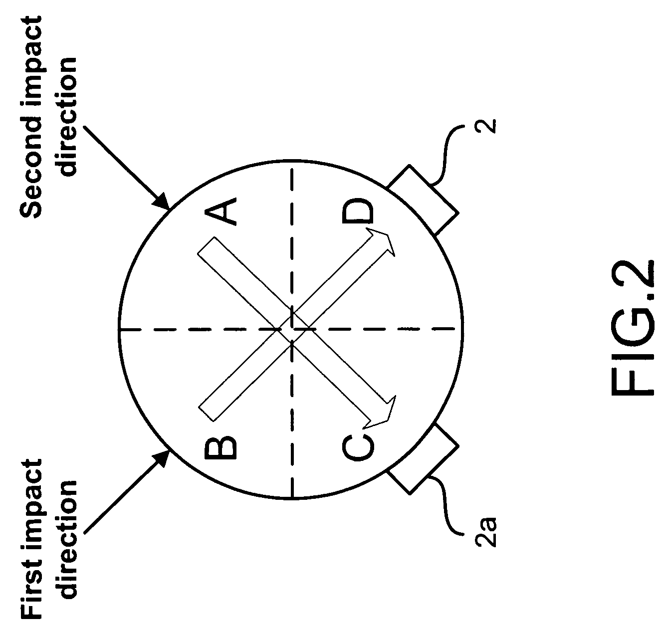
[0010]To achieve the above purpose, the present invention is a method of examining an irregular defect of an implant, comp rising steps of: (a) exciting an implant through a vibrating device to obtain vibration responses; (b) obtaining a frequency response diagram with the vibration responses through a spectral analysis; and (c) obtaining a defect status and an osseointegration stability of the implant by referring to at least one position of at least one vibration accelerometer and differences of resonance frequency of the implant. Accordingly, a novel method of examining an irregular defect of an implant is obtained.

Problems solved by technology

However, only an overall stability of the interface between the implant and an alveolar bone are obtained without indicating specific positions of defect.
Not to mention that clinical examination on a 2-dimensional X-ray image film of the implant is insufficient for the diagnosis of irregular bone defects.
Hence, the prior arts do not fulfill all users' requests on actual use.

Method used


Image

  • Method of examining irregular defects of dental implant
  • Method of examining irregular defects of dental implant
  • Method of examining irregular defects of dental implant

Examples


Embodiment Construction

[0028]The following description of the preferred embodiment is provided to understand the features and the structures of the present invention.

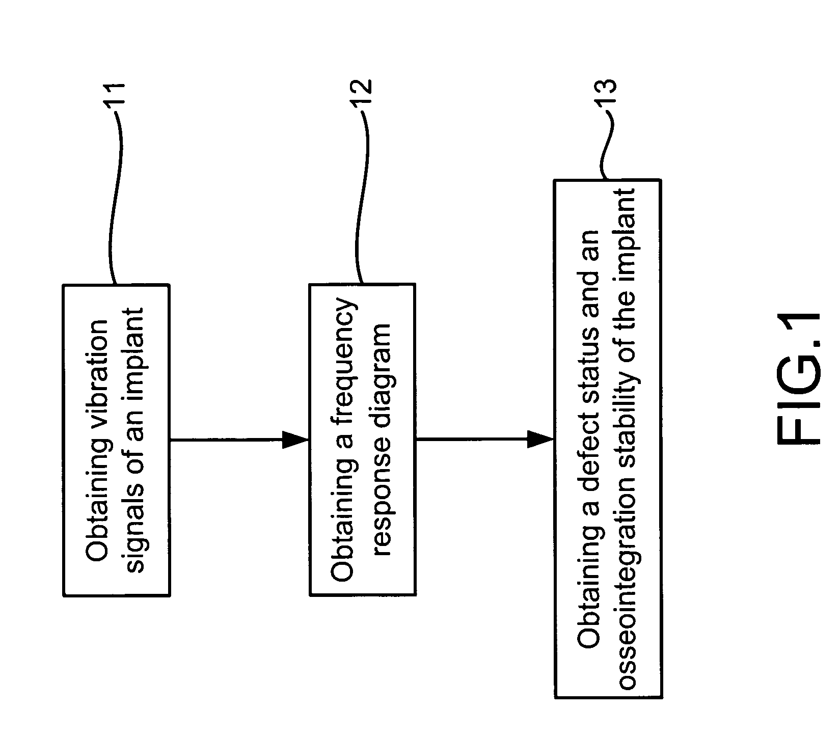
[0029]Please refer to FIG. 1, which is a flow view showing a preferred embodiment according to the present invention. As shown in the figure, the present invention is a method of examining an irregular defect of an implant, comprising the following steps:

[0030](a) Obtaining vibration responses of an implant 11: An implant is excited through a vibrating device, like an impact hammer, for obtaining its vibration responses.

[0031](b) Obtaining a frequency response diagram 12: The vibration responses are processed to obtain a frequency response chart through a spectral analysis.

[0032](c) Obtaining a defect status and an osseointegration stability of the implant 13: By referring to at least one position of at least one vibration sensor and differences of resonance frequency of the implant, a defect status and an osseointegration stability of the im...


PUM

PropertyMeasurementUnit
frequency responseaaaaaaaaaa
osseointegration stabilityaaaaaaaaaa
resonance frequencyaaaaaaaaaa

Abstract

An irregular defect of a dental implant is examined. The dental implant is excited first to obtain vibration responses. The vibration responses is received by accelerometer or sensor to be processed into a resonance frequency diagram. Through the diagram and the position of the accelerometer or sensor, stability of the whole structure and the defect position are diagnosed for evaluation. The present invention can be also applied to implants other than the dental implant.

Description

FIELD OF THE INVENTION[0001]The present invention relates to examining implant defect; more particularly, relates to evaluating irregular defect of an implant through exciting the implant.DESCRIPTION OF THE RELATED ARTS[0002]A first prior art is a U.S. Pat. No. of 5,392,779. The first prior art provides a method and apparatus for the test of an implant attached to a bone of a human or animal subject, where the apparatus comprises a device adapted to be releasably attached to the implant; excitation means for exciting the device with a variable frequency AC excitation signal; and means including a transducer for detecting at least one resonance frequency of the device. The detected resonance frequency is used to assess the degree of attachment of the implant to the bone.[0003]A second prior art is a U.S. Pat. No. of 5,392,779. The second prior art is a dental analyzer, comprising a dental probe for contacting a dental implant; a hammer to impact the dental probe for obtaining vibrati...

Claims


Application Information

Patent Timeline
Patent Type & Authority Applications(United States)
IPC IPC(8): A61C13/00A61B5/00G01N29/12
CPCA61C19/04G01N29/045G01N2291/02483G01N29/46G01N29/4454
Inventor PAN, MIN-CHUNZHUANG, HAN-BOLEE, SHYH-YUAN
Owner NAT CENT UNIV
Learn More