
Cannula with associated filter and methods of use during cardiac surgery

a technology of blood filter and cannula, which is applied in the field of blood filter devices, can solve problems such as complications in the body, and achieve the effects of reducing neurologic, cognitive, cardiac, and neurological complications, reducing the number of complications, and effectively filtering blood

Inactive Publication Date: 2006-03-14
EDWARDS LIFESCIENCES CORP
View PDF38 Cites 81 Cited by
  • Summary
  • Abstract
  • Description
  • Claims
  • Application Information

AI Technical Summary

Benefits of technology

[0022]In still another embodiment, the device includes a cannula made in part of a deformable (e.g.) elastomeric material such that the deformable part of the cannula collapses to absorb the mesh and the corresponding adapted structure upon mesh closure, thereby reducing the profile of the instrument for vessel introduction.
[0023]The methods of the present invention relate to filtering blood flowing within a blood vessel, particularly to entrap embolic material, thereby protecting a patient from embolization. In accordance with one aspect of the method of the invention, a patient is protected from embolization during surgery while performing a procedure affecting a region of an artery of the patient wherein the artery includes foreign matter on an inside surface thereof at least a portion of which is dislodged as a result of mechanical or other forces applied during the procedure, by deploying a removable filtration device in a blood vessel downstream of one affected region of the artery to entrap the dislodged foreign matter.
[0030]Transesophageal echocardiography (TEE), another standard visualization technique known in the art, is significant in the detection of conditions which may predispose a patient to embolization. TEE is an invasive technique, which has been used, with either biplanar and multiplanar probes, to visualize segments of the aorta, to ascertain the presence of atheroma. This technique permits physicians to visualize the aortic wall in great detail and to quantify atheromatous aortic plaque according to thickness, degree of intraluminal protrusion and presence or absence of mobile components, as well as visualize emboli within the vascular lumen. See, for example, Barbut et al., “Comparison of Transcranial Doppler and Transesophageal Echocardiography to Monitor Emboli During Coronary Bypass Surgery,”Stroke 27(1):87–90 (1996) and Yao, Barbut et al., “Detection of Aortic Emboli By Transesophageal Echocardiography During Coronary Artery Bypass Surgery,”Journal of Cardiothoracic Anesthesia 10(3):314–317 (May 1996), and Anesthesiology 83(3A):A126 (1995), which are incorporated herein by reference in their entirety. Through TEE, one may also determine which segments of a vessel wall contain the most plaque. For example, in patients with aortic atheromatous disease, mobile plaque has been found to be the least common in the ascending aorta, much more common in the distal arch and most frequent in the descending segment. Furthermore, TEE-detected aortic plaque is unequivocally associated with stroke. Plaque of all thickness is associated with stroke but the association is strongest for plaques over 4 mm in thickness. See Amarenco et al., “Atherosclerotic disease of the aortic arch and the risk of ischemic stroke,”New England Journal of Medicine, 331:1474–1479 (1994).
[0032]Through visualization techniques such as TEE epicardial aortic ultrasonography and intravascular ultrasound, it is possible to identify the patients with plaque and to determine appropriate regions of a patient's vessel on which to perform certain procedures. For example, during cardiac surgery, in particular, coronary artery bypass surgery, positioning a probe to view the aortic arch allows monitoring of all sources of emboli in this procedure, including air introduced during aortic cannulation, air in the bypass equipment, platelet emboli formed by turbulence in the system and atheromatous emboli from the aortic wall. Visualization techniques may be used in conjunction with a blood filter device to filter blood effectively. For example, through use of a visualization technique, a user may adjust the position of a blood filter device, and the degree of actuation of that device as well as assessing the efficacy of the device by determining whether foreign matter has bypassed the device.
[0033]It is an object of the present invention to eliminate or reduce the problems that have been recognized as relating to embolization. The present invention is intended to entrap and remove emboli in a variety of situations. For example, in accordance with one aspect of the invention, blood may be filtered in a patient during procedures which affect blood vessels of the patient. The present invention is particularly suited for temporary filtration of blood in an artery of a patient to entrap embolic debris. This in turn will eliminate or reduce neurologic, cognitive, and cardiac complications helping to reduce length of hospital stay. In accordance with another aspect of the invention, blood may be filtered temporarily in a patient who has been identified as being at risk for embolization.
[0034]As for the devices, one object is to provide simple, safe and reliable devices that are easy to manufacture and use. A further object is to provide devices that may be used in any blood vessel. Yet another object is to provide devices that will improve surgery by lessening complications, decreasing the length of patients' hospital stays and lowering costs associated with the surgery. See Barbut et al., “Intraoperative Embolization Affects Neurologic and Cardiac Outcome and Length of Hospital Stay in Patients Undergoing Coronary Bypass Surgery,”Stroke (1996).

Problems solved by technology

Embolic material or foreign matter is any particulate matter which may cause complications in the body if allowed to travel freely in the bloodstream.

Method used


Image

  • Cannula with associated filter and methods of use during cardiac surgery
  • Cannula with associated filter and methods of use during cardiac surgery
  • Cannula with associated filter and methods of use during cardiac surgery

Examples


Embodiment Construction

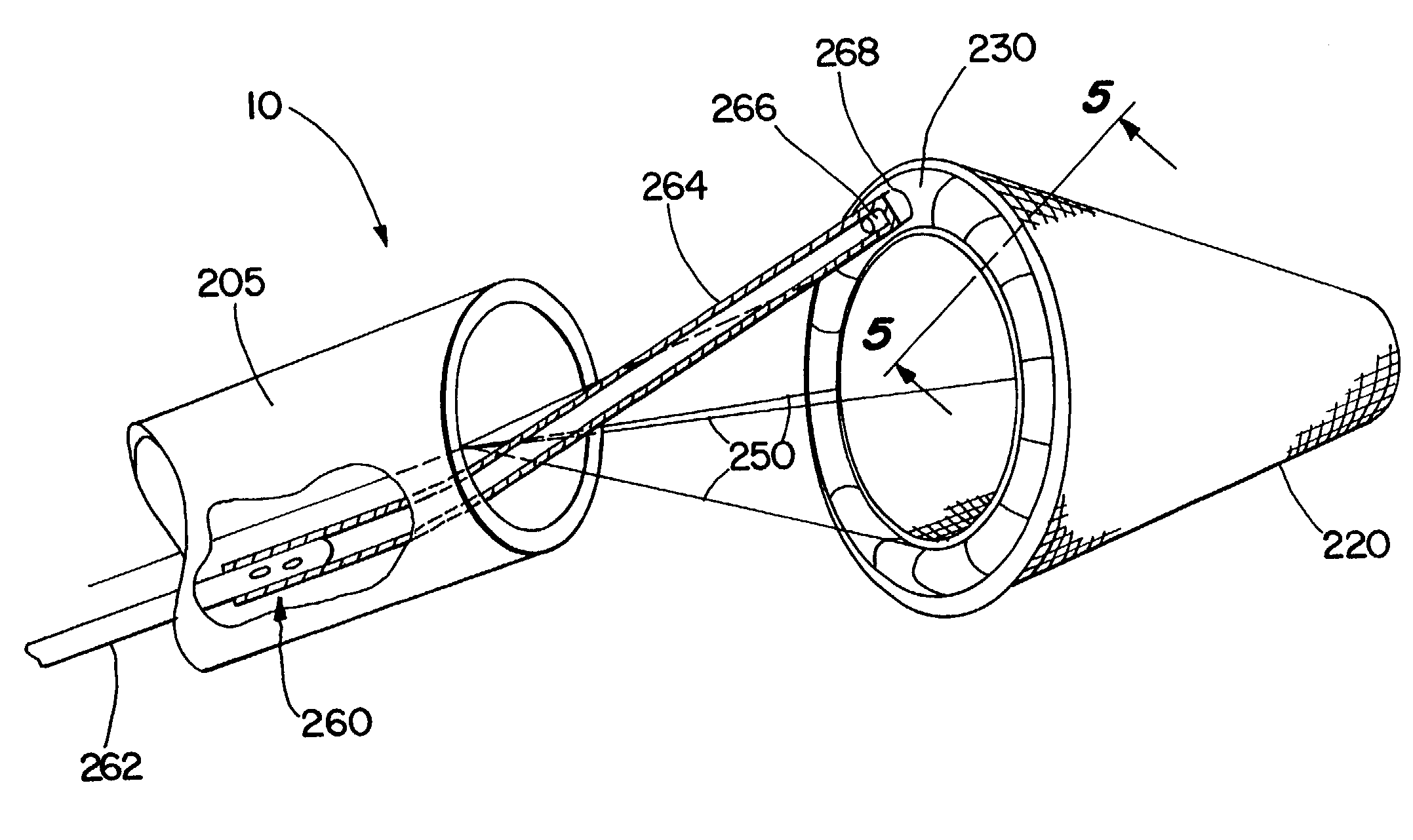
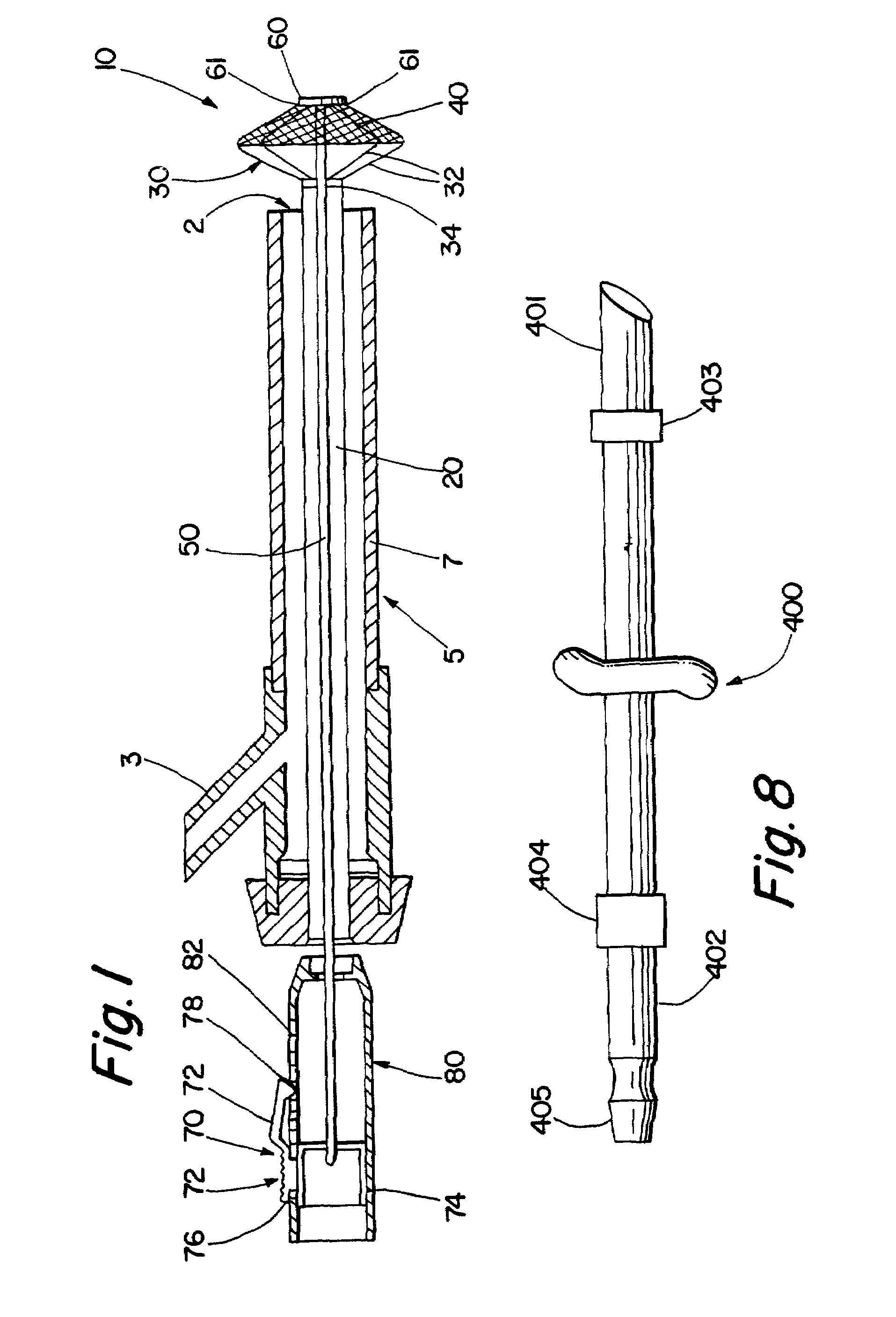
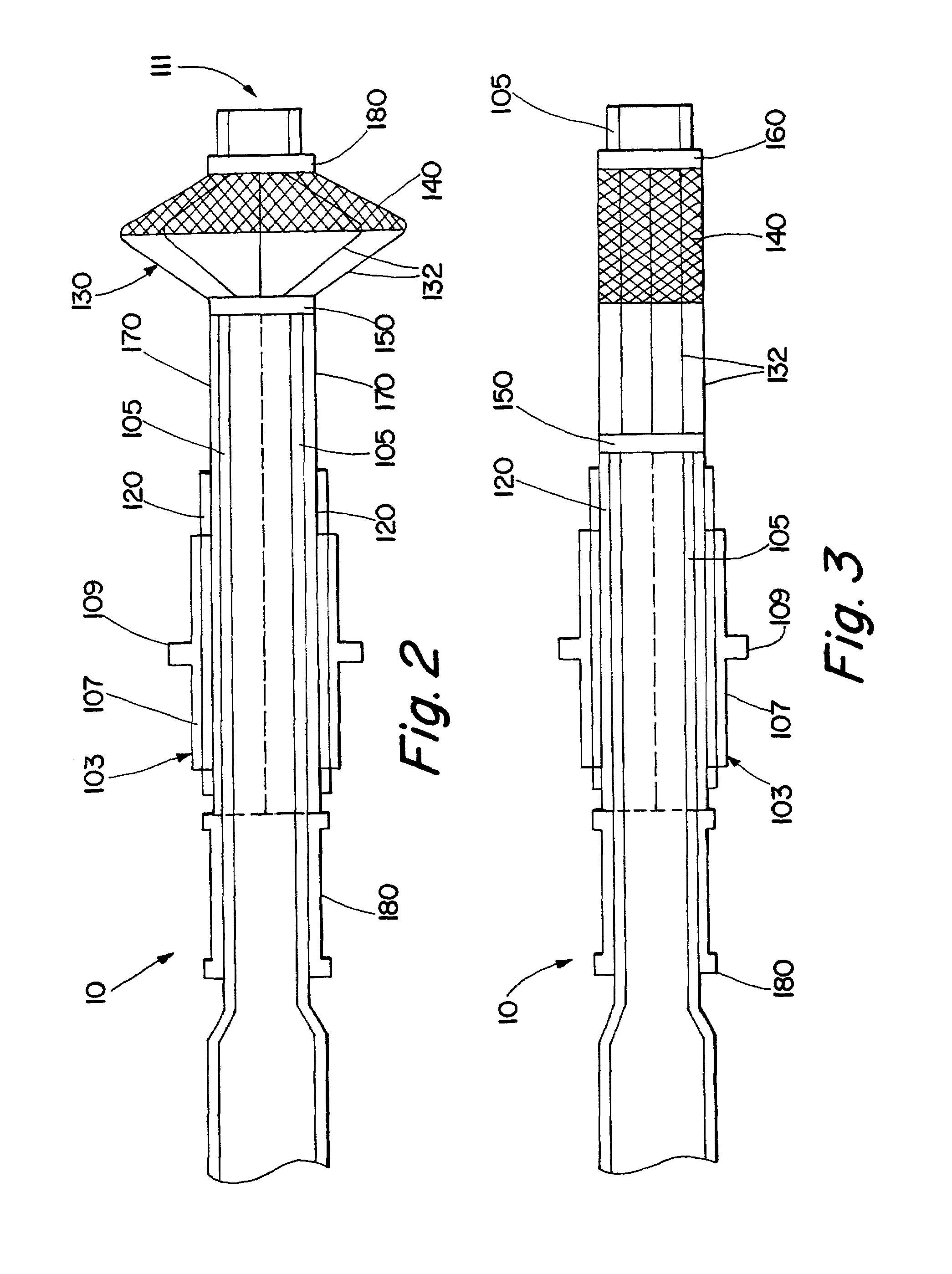
[0068]Referring more particularly to the drawings, FIG. 1 shows one embodiment of the blood filter device for use herein. The blood filter device 10 comprises an insertion tube 20, an umbrella frame 30, and an end plate 60, an activation tube 50, a mesh 40, an adjustment device 70, and a handle 80.

[0069]The device 10 is introduced into a vessel through a main port 7 of a cannula 5, and blood or other surgical equipment may be introduced into the main port 7 of the cannula 5 through a side port 3. The cannula 5 and the device 10 will not interfere with placement of equipment which may be used during a surgical procedure.

[0070]As shown in FIG. 1, the umbrella frame 30 comprises a plurality of arms 32 (some of which are not shown), which may include 3 arms, more preferably 4 arms, more preferably 5 arms, more preferably 6 arms, more preferably 7 arms, more preferably 8 arms, more preferably 9 arms, and most preferably 10 arms. The arms are sonically welded to a socket 34, which in turn...


PUM


Abstract

Devices and methods for filtering blood. The devices generally comprise a mesh for filtering blood flowing within a blood vessel, particularly within an artery such as the aorta, a structure adapted to open and close the mesh within the blood vessel, and a means to actuate the structure. The methods generally include the steps of introducing a mesh into a blood vessel to entrap embolic material, and removing the mesh and the entrapped foreign matter from the blood vessel.

Description

[0001]This is a division of U.S. application Ser. No. 09 / 691,641, filed Oct. 18, 2000 now U.S. Pat. No. 6,423,086, which is a continuation of U.S. application Ser. No. 09 / 455,874, filed Dec. 6, 1999, now U.S. Pat. No. 6,235,045, which is a continuation of U.S. application Ser. No. 09 / 336,372, filed Jun. 17, 1999, now U.S. Pat. No. 6,117,154, which is a continuation of U.S. application Ser. No. 08 / 842,727, filed Apr. 16, 1997, now U.S. Pat. No. 5,989,281, which is a continuation-in-part of U.S. application Ser. No. 08 / 640,015, filed Apr. 30, 1996, now U.S. Pat. No. 5,769,816, which is a continuation-in-part of U.S. application Ser. No. 08 / 584,759, filed Jan. 11, 1996, now abandoned, which is a continuation-in-part of U.S. application Ser. No. 08 / 580,223, filed Dec. 28, 1995, now abandoned, which is a continuation-in-part of U.S. application Ser. No. 08 / 553,137, filed Nov. 7, 1995, now abandoned. Each of the above-identified applications and patents are expressly incorporated herein b...

Claims


Application Information

Patent Timeline
Patent Type & Authority Patents(United States)
IPC IPC(8): A61M29/00A61F2/01A61F2/02
CPCA61F2/013A61F2002/011A61F2250/0003A61F2230/0067A61F2002/018A61F2230/0006A61M2210/127A61F2/011
Inventor BARBUT, DENISEMAAHS, TRACY D.
Owner EDWARDS LIFESCIENCES CORP
Learn More