Electric vacuum cleaner

a vacuum cleaner and electric technology, applied in the field of electric vacuum cleaners, can solve the problems of increasing the size of the suction device, prone to tangle with hair, lint, hair, etc., and achieve the effect of increasing the suction force of the electric blower fan to a high level, excellent operability, and excellent operability

Inactive Publication Date: 2008-08-28
SANYO ELECTRIC CO LTD
View PDF3 Cites 14 Cited by
  • Summary
  • Abstract
  • Description
  • Claims
  • Application Information

AI Technical Summary

Benefits of technology

[0019]This provides for automatic removal of the sheet wound about the rotary brush. Thus, the invention can offer an electric vacuum cleaner excellent in operability.
[0020]The sheet-removal controlling unit may increase the suction force of the electric blower fan to a high level.
[0021]As the suction force of the electric blower is set to the high level, the electric vacuum cleaner can utilize the strong suction force of the electric blower fan for automatically removing the sheet. Thus, the invention can offer an electric vacuum cleaner excellent in operability.

Problems solved by technology

The rotary brush of the suction device is prone to become tangled with hair, lint and the like in conjunction with a cleaning operation.
This is troublesome.
However, Japanese Unexamined Patent Publication No. 05-192277 (1993) does not suggest that the hair, lint and the like tangled about the rotary brush can be removed by switching the rotation of the rotary brush between the two directions.
However, the arrangement of this patent document has a problem that the suction device is increased in size because the device comprises a roller only for winding the wet sheet thereabout.
However, this arrangement has a problem that a soiled sheet must be manually removed after the wipe off cleaning is finished, which causes discomfort to the user.

Method used


Image

  • Electric vacuum cleaner
  • Electric vacuum cleaner
  • Electric vacuum cleaner

Examples


Embodiment Construction

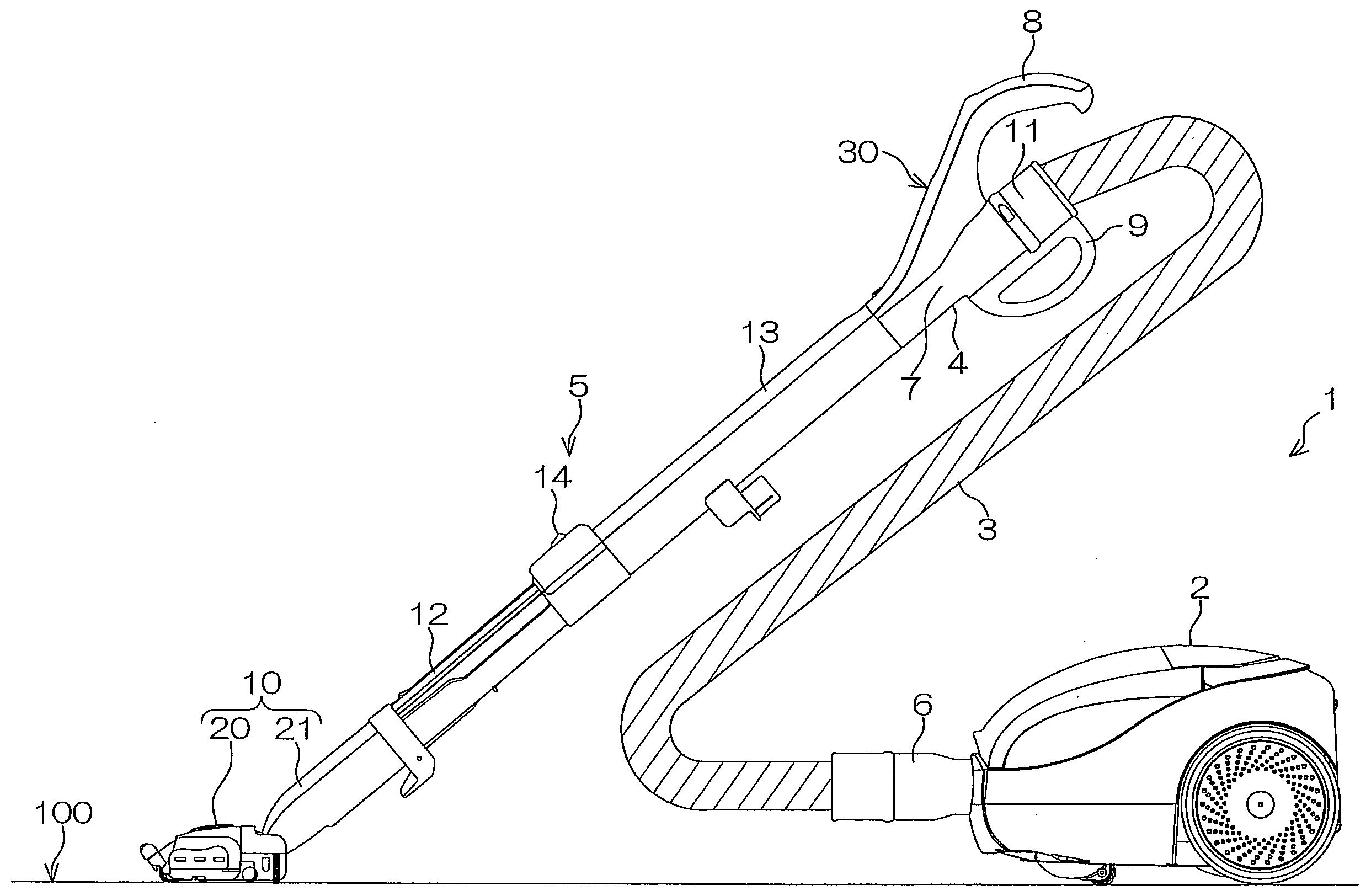
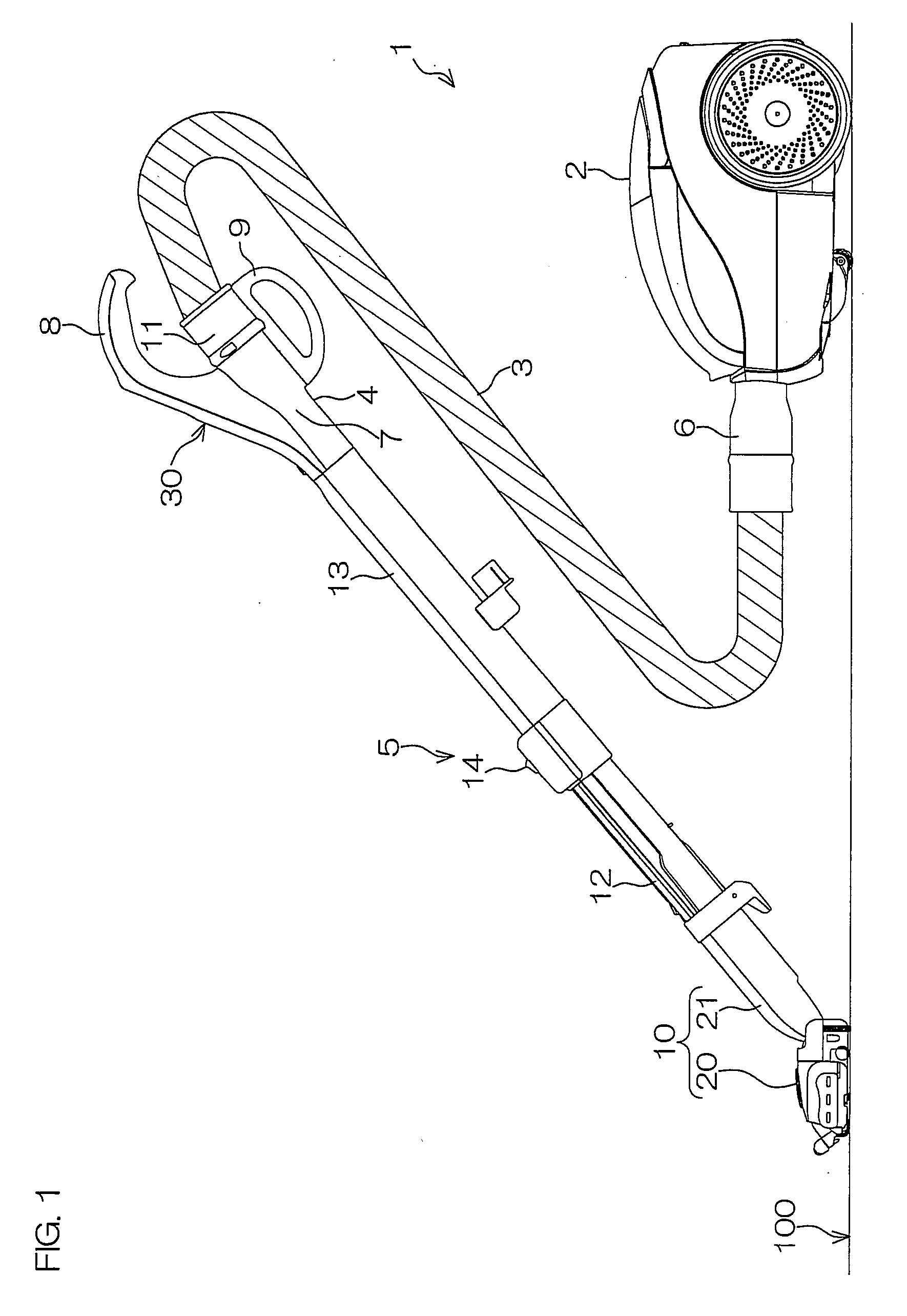
[0074]FIG. 1 is a right side view of an electric vacuum cleaner 1 according to one embodiment of the invention.

[0075]For convenience, the following description is made on the assumption that the left-hand side in FIG. 1 means the front side, the right-hand side therein means the rear side, the near side therein means the left side, the far side therein means the right side, the upper side therein means top and the lower side therein means bottom. The description on the individual components of the electric vacuum cleaner 1 is also made while distinguishing front and rear, right and left, and top and bottom based on the above directional definition.

[0076]The electric vacuum cleaner 1 includes a cleaner body 2, a suction hose 3, an operation portion 4, a suction pipe 5 and a suction device 10.

[0077]The cleaner body 2 incorporates therein an electric blower fan (indicated at 42 in FIG. 3), which generates suction force. A connecting portion 6 disposed at one end (rear end) of the sucti...


PUM


Abstract

An electric vacuum cleaner (1) of the invention is adapted for wipe off cleaning using a sheet wound about a rotary brush (25) incorporated in a suction device (10). In order to wind a sheet (50) around a periphery of the rotary brush (25), a brush motor (44) rotates the rotary brush (25) in a predetermined direction at a predetermined rotational speed. At the same time, suction force of an electric blower fan (42) is set to the lowest level. This achieves the following advantage in a case where a wet sheet is used as the sheet (50). During sheet winding, water and alcohol released from the wet sheet (50) can be prevented from being scattered on a surface (100) to be cleaned. Further, the released water and alcohol do not adversely affect the electric blower fan (42).

Description

BACKGROUND OF THE INVENTION[0001]1. Field of the Invention[0002]The present invention relates to an electric vacuum cleaner. More particularly, the invention relates to an electric vacuum cleaner wherein a suction device incorporating therein a rotary brush driven by a motor is used as a suction device for sucking dirt and dust from a surface to be cleaned.[0003]2. Description of Related Art[0004]The electric cleaner generally includes an electric cleaner body for generating suction force, and the suction device attached to the cleaner body by unit of hose and pipe. The suction device known in the art includes a suction port opposed to the surface to be cleaned and incorporates the rotary brush in the suction port.[0005]The rotary brush of the suction device is prone to become tangled with hair, lint and the like in conjunction with a cleaning operation. A proposal for easily removing the hair, lint and the like tangled about the rotary brush has been made by Japanese Unexamined Pat...

Claims


Application Information

Patent Timeline
Patent Type & Authority Applications(United States)
IPC IPC(8): A47L5/00A47L9/00
CPCA47L9/0477A47L9/0488A47L9/2805A47L9/2842A47L9/2847A47L9/2857Y02B40/82A47L11/202A47L11/4041A47L11/4044A47L11/4047A47L11/4069A47L9/2889Y02B40/00A47L9/02A47L9/04
Inventor NAKAI, KOUICHIKODERA, SADAKIFUKUMOTO, AKIHIROMATSUMOTO, CHIZUYOMORITA, AKIHIROSHIKANO, HIROTAKATSUCHIDA, HIDEYAMATSUMOTO, YOSHIAKIMUKUMOTO, EIJIINUI, SHIGEKI
Owner SANYO ELECTRIC CO LTD
Why Eureka
Try Eureka