
Flat yoke valve actuator

a technology of actuator and yoke, which is applied in the direction of valve details, valve arrangement, gearing, etc., can solve the problems of affecting the drive mechanism of the push rod, the force applied by the push rod to the yoke is not applied, and the bushings wear and eventually fail,

Active Publication Date: 2008-08-28
HOLTGRAVER EDWARD GEORGE
View PDF10 Cites 20 Cited by
  • Summary
  • Abstract
  • Description
  • Claims
  • Application Information

AI Technical Summary

Benefits of technology

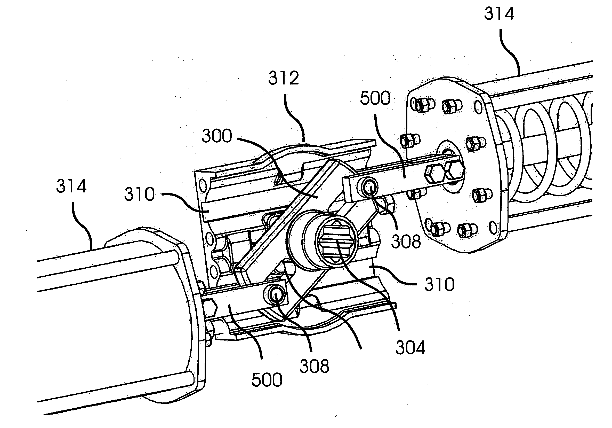
[0009]A Scotch yoke actuator is disclosed that includes a dual yoke with a center and two ends. The two ends are symmetric about the center and each end is penetrated by a yoke slot. A rotatable shaft is fixed to the center of the dual yoke and oriented perpendicular to a plane that contains the yoke slots, and a pair of pushing shafts is coupled respectively to the two ends of the dual yoke. A pair of pushing devices is able respectively to apply equal and opposing forces to the two pushing shafts, thereby applying equal and opposing forces respectively to the two ends of the dual yoke, causing end loading forces applied to the rotatable shaft to be cancelled and eliminated. In preferred embodiments, the center of mass of the two pushing devices is located at the center of the dual yoke, causing the weight of the two pushing devices to be balanced about the center of the dual yoke.
[0011]In preferred embodiments, the pushing shafts are coupled to the ends of the dual yoke by yoke pins that extend through the yoke slots and through holes in the pushing shafts. In some of these preferred embodiments, the yoke pins include rollers, bearings, and / or other mechanisms that are able to reduce friction between a yoke pin and a yoke slot. In other of these preferred embodiments, two pair of yoke pin slots support and guide protruding ends of the two yoke pins as the rotatable shaft rotates. In some of these embodiments, the yoke pin slots are formed in faces of a housing that surrounds the dual yoke, and in some of these embodiments at least one end of each yoke pin slot extends to an edge of the housing face in which it is formed, thereby allowing for easy removal and reinstallation of the pushing shafts and yoke pins without complete disassembly of the dual yoke housing or removal of the dual yoke from the rotatable shaft.

Problems solved by technology

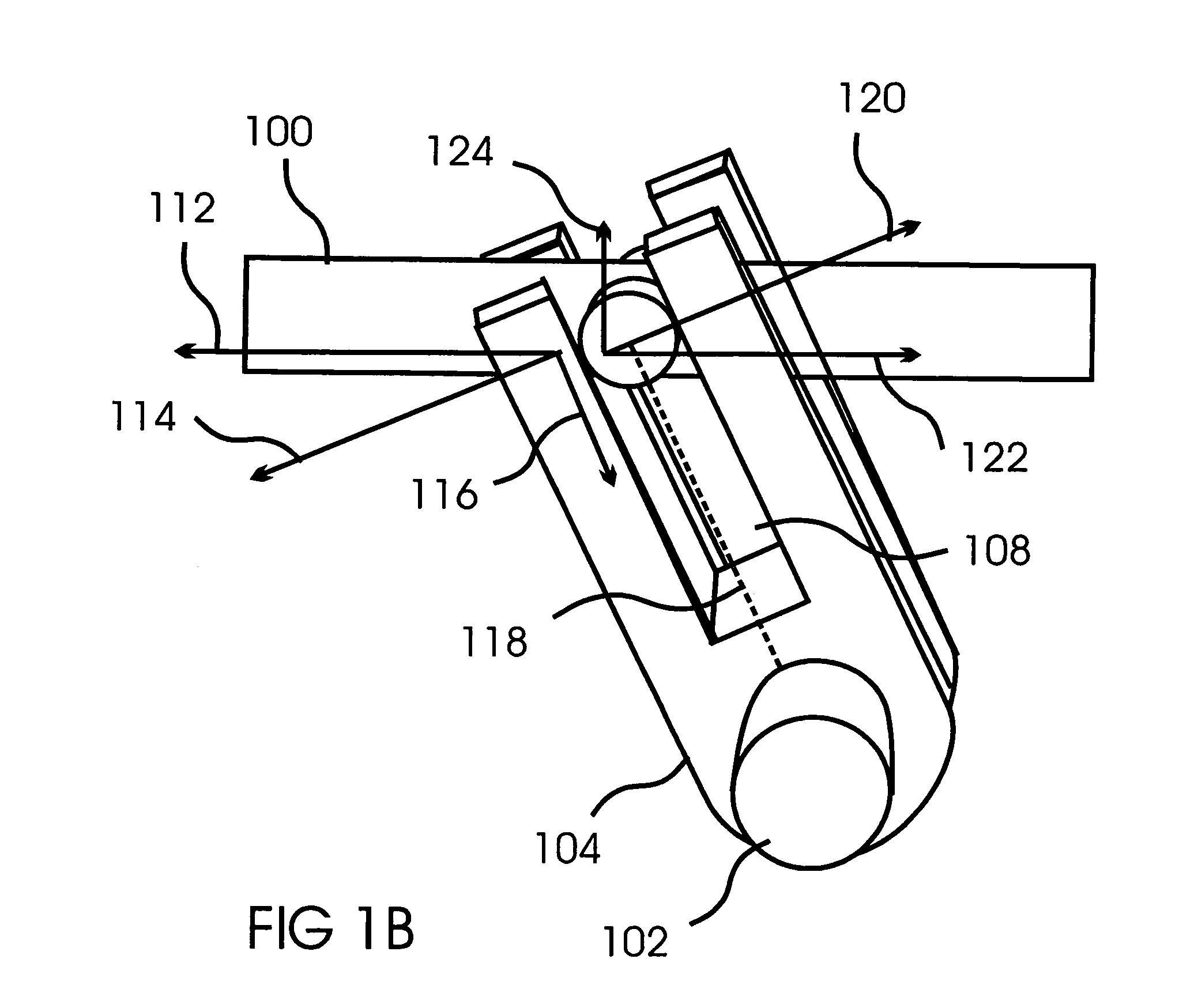
A significant disadvantage of the Scotch yoke design is that during most of its 90 degree rotation the force applied by the push rod to the yoke is not perpendicular to the axis of the yoke (the axis of the yoke being defined as an imaginary line that joins the shaft to the yoke pin).
But significant side loading force combined with constant sliding of the push rod past the support bushings can cause the bushings to wear and eventually to fail.
Also, the side loading force can be transmitted past the support bushings by a lever effect and can damage the piston, spring, or other mechanism that drives the push rod.
In addition, the friction between the support bushings and the push rod can cause “jump starts” and uneven movement of the push rod, making the design unsuitable for applications such as valve throttles that require smooth, controllable movement.
This approach avoids the wear, unsmooth movement, and other problems associated with push rod support bushings, but does not eliminate side loading of the rotatable shaft, which can cause wearing and failing of the bushings or other structures that support the shaft.
Any tendency of the push rod to rotate can cause misalignment of the pin, and even failure of the coupling.
Even if slots in a yoke housing are used to maintain the orientation of the yoke pin, rotational tendencies of the push rod can cause wear to the yoke pin and to the yoke pin hole.

Method used


Image

  • Flat yoke valve actuator
  • Flat yoke valve actuator
  • Flat yoke valve actuator

Examples


Embodiment Construction

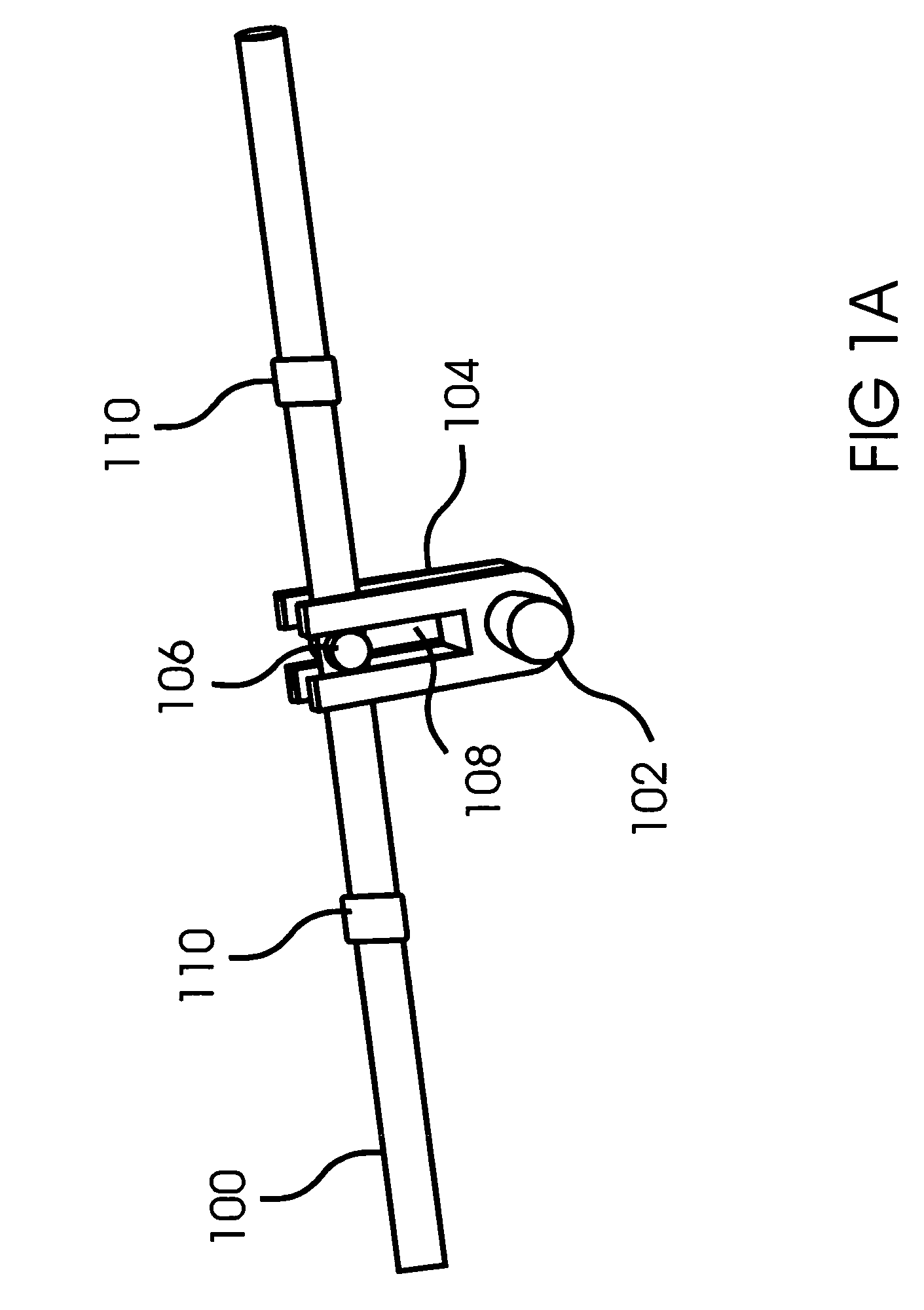
[0021]With reference to FIG. 1A, in a typical Scotch yoke design a push rod 100 moves back and forth past a rotatable shaft 102 that is offset from the rod and perpendicular to it. The push rod 100 is coupled to the shaft by a lever arm or yoke 104 that converts the linear movement of the rod 100 to a rotary movement of the shaft 102, with a normal rotation angle of approximately 90 degrees. The push rod is coupled to the yoke by a yoke pin 106 that passes through a hole in the push rod and a slot 108 in the yoke 104, thereby allowing the yoke pin 106 to slide along the slot 108 as the push rod 100 moves and the yoke 104 and shaft 102 rotate. Two push rod support bushings 110 resist the side loading forces applied to the push rod 100 and maintain the orientation of the push rod 100.

[0022]FIG. 1B illustrates the forces that are applied by the push rod 100 to the yoke 104, and the reactive forces applied by the yoke 104 to the push rod 100. The push rod 100 applies a force 112 to the ...


PUM


Abstract

A Scotch yoke actuator is disclosed with a dual yoke and a diagonally symmetric design. A pair of shafts and pushing devices apply equal, opposing forces to the yoke, causing end loading forces applied to a rotatable shaft attached to the center of the yoke to be cancelled. In embodiments, the weight of the pushing devices is balanced about the yoke, each shaft extends in only one direction from the yoke, and / or the shafts are supported only by the yoke and the pushing devices. In embodiments that use yoke pins, the yoke pins include rollers or bearings to reduce friction, and / or two pair of yoke pin slots support protruding ends of the yoke pins. The yoke pin slots can extend to edges of a yoke housing face, allowing easy shaft removal and reinstallation, and each shaft can include a split end with extensions on opposing sides of the yoke.

Description

CROSS-REFERENCE TO RELATED APPLICATIONS[0001]This application is entitled to the benefit of U.S. Provisional Patent Application No. 60 / 903,860 entitled “Flat Yoke Valve Actuator,” filed Feb. 24, 2007 by Edward George Holtgraver, herein incorporated by reference.FIELD OF THE INVENTION[0002]The invention generally relates to devices that convert linear motion to rotary motion, and more specifically to Scotch yoke actuators.BACKGROUND OF THE INVENTION[0003]A common mechanism for converting linear motion to quarter-turn rotary motion is the Scotch yoke actuator. A Scotch yoke actuator provides a rotation of approximately 90 degrees, with a torque that is higher at the ends of travel and lower in the middle. This is beneficial for operating valves that have higher torque requirements at the fully closed position. Also, Scotch yoke actuators are generally less costly to manufacture than other actuator designs when a torque output of greater than 15,000 inch-pounds is required, making the ...

Claims


Application Information

Patent Timeline
IPC IPC(8): F16K31/44
CPCF16K31/1635Y10T74/18256Y10T74/18248
Inventor HOLTGRAVER, EDWARD GEORGE
Owner HOLTGRAVER EDWARD GEORGE
Learn More