
Pressure Support System with Automatic Comfort Feature Modification

a technology of automatic comfort and support system, which is applied in the direction of valve operating means/release devices, process and machine control, instruments, etc., can solve the problems of severe oxyhemoglobin desaturation, disordered breathing, and fragmentation of sleep, and achieve the effect of reducing the number of patients

Active Publication Date: 2008-08-28
PHILIPS RS NORTH AMERICA LLC
View PDF41 Cites 102 Cited by
  • Summary
  • Abstract
  • Description
  • Claims
  • Application Information

AI Technical Summary

Benefits of technology

[0017]Accordingly, it is an object of the present invention to provide a pressure support system that overcomes the shortcomings of conventional pressure support systems. This object is achieved according to one embodiment of the present invention by providing a pressure support system that includes a pressure generating system adapted to generate a pressurized flow of gas, a patient circuit coupled to the pressure generating system and adapted to communicate the flow of gas to an airway of a patient, and a controller. The controller receives a treatment set point from an input source and is programmed to determine an adjusted treatment set point based on the treatment set point and a comfort feature function. The comfort feature function is a formula, algorithm, or other implementation scheme, not based on a physiological condition of such a patient, that dictates how and when to add, delete, or modify a comfort feature of the underlying respiratory treatment therapy being provided to the patient. The controller controls the operation of the pressure generating system based on the adjusted treatment set point.
[0017]Accordingly, it is an object of the present invention to provide a pressure support system that overcomes the shortcomings of conventional pressure support systems. This object is achieved according to one embodiment of the present invention by providing a pressure support system that includes a pressure generating system adapted to generate a pressurized flow of gas, a patient circuit coupled to the pressure generating system and adapted to communicate the flow of gas to an airway of a patient, and a controller. The controller receives a treatment set point from an input source and is programmed to determine an adjusted treatment set point based on the treatment set point and a comfort feature function. The comfort feature function is a formula, algorithm, or other implementation scheme, not based on a physiological condition of such a patient, that dictates how and when to add, delete, or modify a comfort feature of the underlying respiratory treatment therapy being provided to the patient. The controller controls the operation of the pressure generating system based on the adjusted treatment set point.

Problems solved by technology

It is well known that many individuals suffer from disordered breathing during sleep.
Those afflicted with OSA experience sleep fragmentation and complete or nearly complete cessation of ventilation intermittently during sleep with potentially severe degrees of oxyhemoglobin desaturation.
Sleep apnea sufferers may be at risk for excessive mortality from these factors as well as by an elevated risk for accidents while driving and / or operating potentially dangerous equipment.
Even if a patient does not suffer from a complete obstruction of the airway, it is also known that adverse effects, such as arousals from sleep, can occur where there is only a partial obstruction of the airway.
Partial obstruction of the airway typically results in shallow breathing, which is referred to as a hypopnea.
Changing the rise / fall time is done based on the physiological condition of the patient detected by flow, pressure, or other sensors, and may not result in an optimization of the comfort of the overall pressure support therapy.

Method used


Image

  • Pressure Support System with Automatic Comfort Feature Modification
  • Pressure Support System with Automatic Comfort Feature Modification
  • Pressure Support System with Automatic Comfort Feature Modification

Examples


Embodiment Construction

A. System Hardware

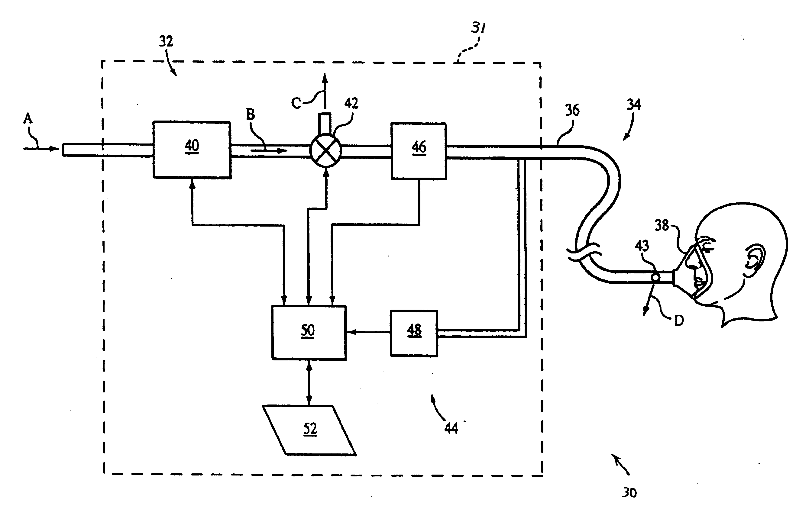
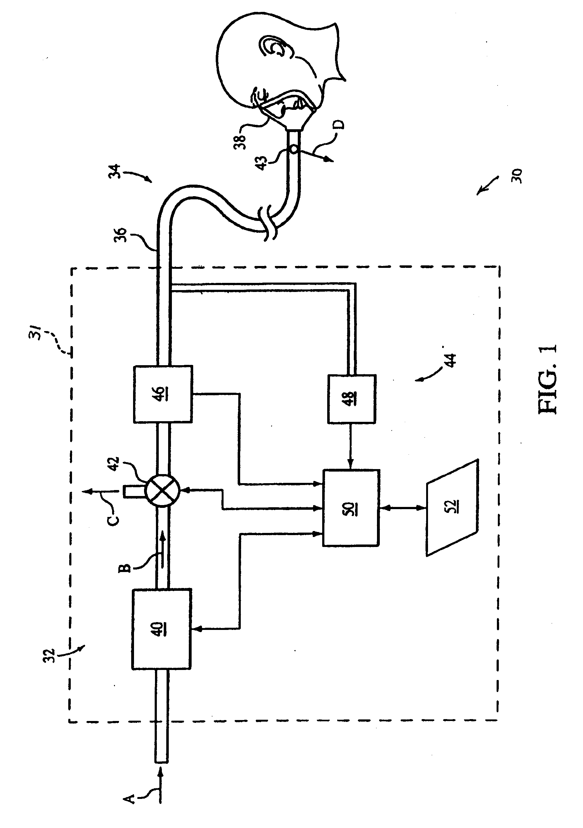
[0025]FIG. 1 schematically illustrates an exemplary embodiment of a pressure support system 30 according to the principles of the present invention. Pressure support system 30 includes a pressure generating system, generally indicated at 32, and a patient circuit 34. Patient circuit 34 includes a conduit 36 and a patient interface device 38. In the illustrated embodiment, pressure generating system 32 includes a pressure generator 40 and a pressure control valve 42 coupled to the outlet of the pressure generator. A housing, indicated by dashed line 31, contains many of the components of the pressure support system.

[0026]Pressure generator 40 receives breathing gas from a source of breathing gas, as indicated by arrow A, and outputs the breathing gas, as indicated by arrow B, to patient circuit 34 at a pressure that is greater than atmosphere for delivery to the airway of a patient.

[0027]In a preferred embodiment of the present invention, pressure generator 40 is a ...


PUM


Abstract

A pressure support system that delivers a flow of gas to a patient's airway via a pressure generating system and a patient circuit. A controller receives a treatment set point from an input source and determines an adjusted treatment set point based on the treatment set point and a comfort feature function, which in one embodiment, is not based on a physiological condition of such a patient. In another embodiment, the controller provides a respiratory treatment therapy during a therapy session based on the treatment set point and the comfort feature, which is modified automatically during a therapy session without user intervention based on a comparison of the treatment set point to a treatment set point variable. The controller controls the operation of the pressure generating system based on the adjusted treatment set point or the combination of the treatment set point and the comfort feature.

Description

CROSS-REFERENCE TO RELATED APPLICATIONS[0001]This application claims priority under 35 U.S.C. § 119(e) from provisional U.S. patent application No. 60 / 900,943 filed Feb. 12, 2007 the contents of which are incorporated herein by reference.BACKGROUND OF THE INVENTION[0002]1. Field of the Invention[0003]The present invention pertains to a pressure support system to treat disordered breathing, and, in particular, to such a system that automatically maximizes the comfort of the respiratory treatment therapy delivered to a patient during a therapy session.[0004]2. Description of the Related Art[0005]It is well known that many individuals suffer from disordered breathing during sleep. Examples of sleep disordered breathing include apneas, hypopneas, flow limitations, and Chynes-Stokes respiration. Apneas can be central apneas, which is the result of a loss of a drive to breathe, obstructive apneas, which is the result of a mechanical obstruction of the airway, or mixed (central and obstruc...

Claims


Application Information

Patent Timeline
Patent Type & Authority Applications(United States)
IPC IPC(8): A61M16/00A62B7/00
CPCA61M16/0051A61M2205/50A61M2016/0036A61M2016/0027A61M16/0063A61M16/026
Inventor CARTER, DUANE H.DIXON, TIMJONCZAK, DANIEL A.PAUL, ZACHARYSHELLY, BENJAMIN I.MATTHEWS, GREGHILL, PETER D.DEGUILIO, ANDREW
Owner PHILIPS RS NORTH AMERICA LLC
Features
  • Generate Ideas
  • Intellectual Property
  • Life Sciences
  • Materials
  • Tech Scout
  • Unparalleled Data Quality
  • Higher Quality Content
  • 60% Fewer Hallucinations
Learn More