Display bar assembly for merchandising displays

a technology for display bars and display bars, which is applied in washstands, curtain suspension devices, lighting support devices, etc., can solve the problems of display bars with a single mounting bracket are useless, and mounting brackets are easily separated and lost or misplaced relative to display bars, etc., to achieve easy best fit and wide width

Active Publication Date: 2008-08-28
TRION IND
View PDF6 Cites 23 Cited by
  • Summary
  • Abstract
  • Description
  • Claims
  • Application Information

AI Technical Summary

Benefits of technology

[0007]In one preferred embodiment of the invention, the mounting brackets are each provided with a pair of angularly oriented mounting hooks arranged to be received in slots in the spaced uprights, as a means for attaching the display bar assembly to the uprights. The slot-engaging hooks are of generally L-shaped configuration defining, with an edge of the bracket, an open ended recess for receiving wall material of the upright, when the hook is engaged in a slot on the upright. To advantage, the two hooks are positioned on adjacent side edges of the brackets, ori

Problems solved by technology

A serious disadvantage of these prior art devices is that the mounting brackets are separable from the display bar.
Accordingly, when the display facilities are removed from the uprights, and reused elsewhere or stored between uses, the mounting brackets easily can become separated and lost or misplaced relative to the display b

Method used


Image

  • Display bar assembly for merchandising displays
  • Display bar assembly for merchandising displays
  • Display bar assembly for merchandising displays

Examples


Embodiment Construction

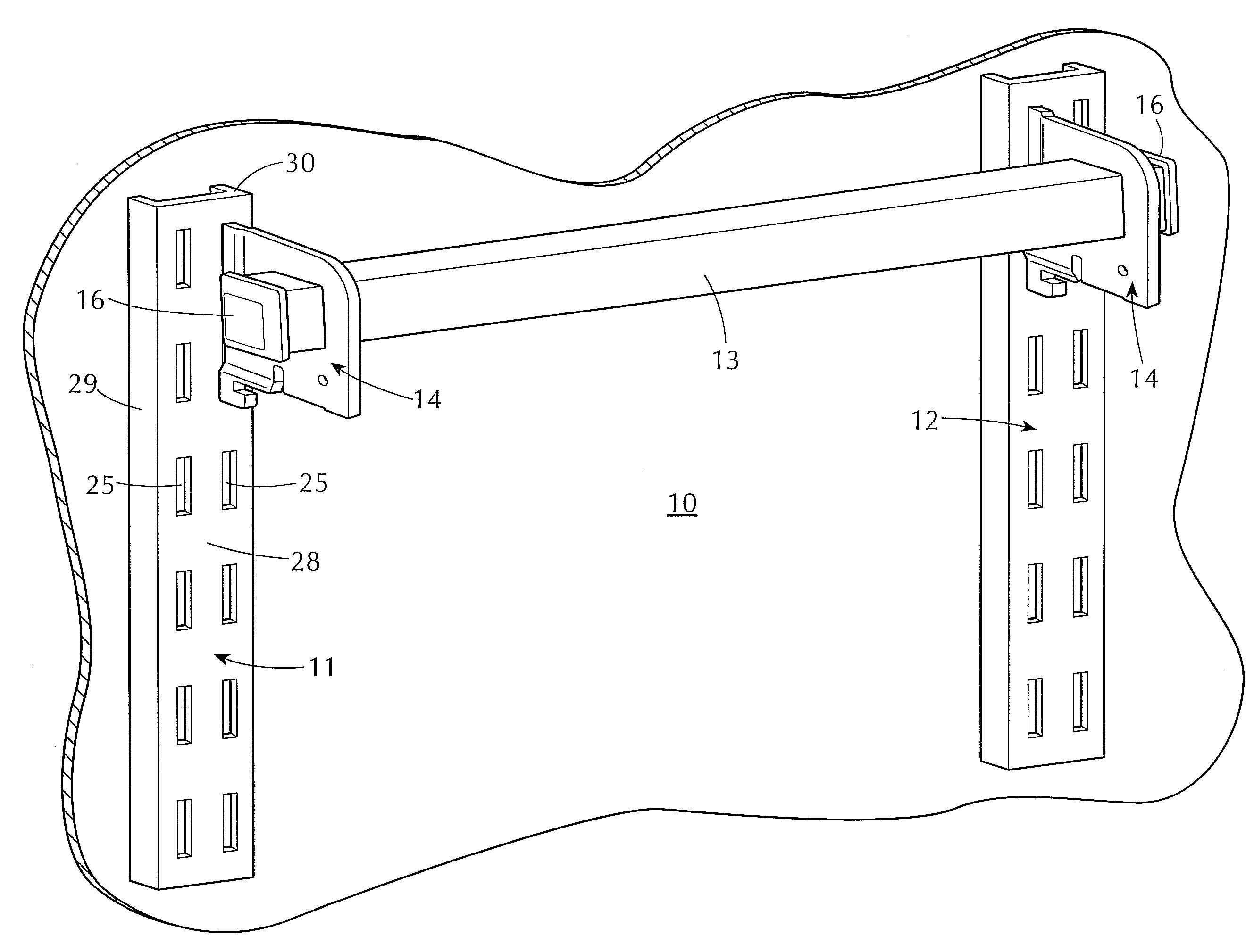
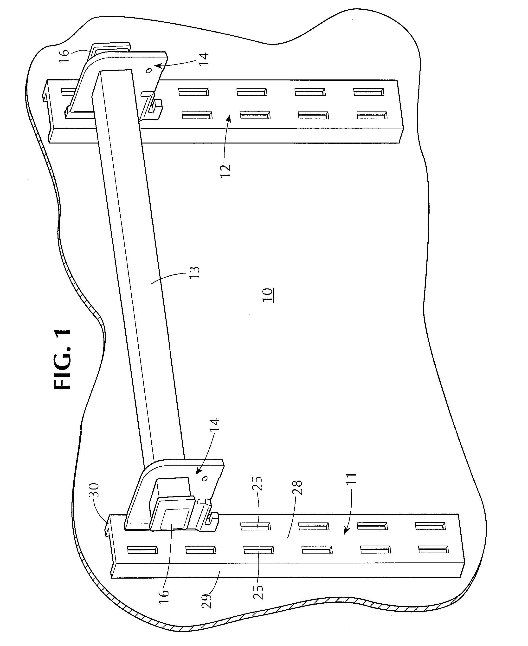
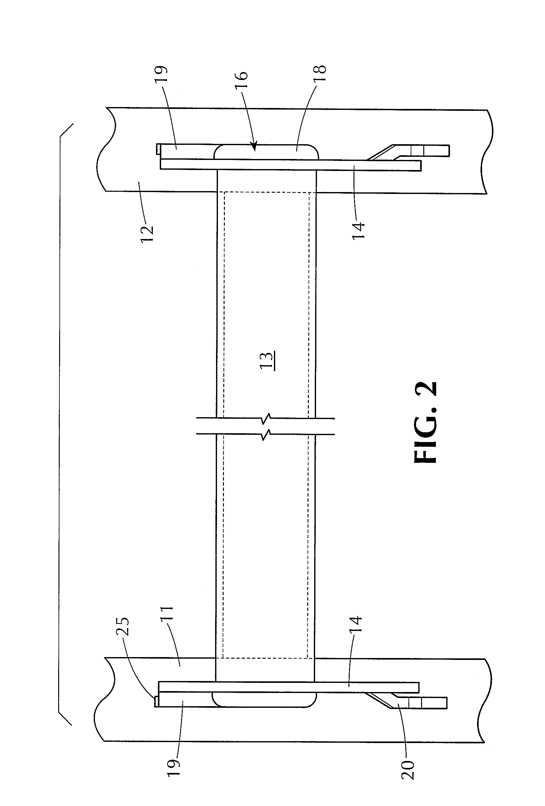
[0019]Referring now to the drawings, the reference numeral 10 designates generally a display wall, which can be a gondola, for example, or simply a vertical wall structure. Mounted on the wall 10 are spaced apart slotted uprights 11, 12, which are suitably secured to the wall 10 and extend vertically more or less along its entire vertical extent. Typical merchandise display arrangements tend to use somewhat standardized spacings for the uprights 11, 12, for example approximately thirty inches, thirty-six inches and forty-eight inches. The uprights can be used for mounting a wide variety of display devices, such as shelf-supporting brackets, bins, etc. and including display bars such as shown at 13 in FIG. 1. Typically, the display bars themselves are used to mount hooks or other devices on which merchandise can be suspended and displayed.

[0020]At each end of the display bar 13 is a mounting bracket 14, to be described further, by which the display bar 13 is mounted on and secured to...


PUM


Abstract

A display bar assembly for mounting on spaced apart slotted uprights on a merchandising gondola or the like. A tubular display bar of polygonal cross section is fitted with a pair of mounting brackets, which are slideable along the bar to enable spacing of the mounting brackets to agree with the spacing between the slotted uprights, which can be somewhat variable. The mounting brackets are formed with openings which closely and non-rotatably receive the display bar and are provided with hooks which engage slots in the uprights. Flanged end plugs are received tightly in each end of the display bar to prevent removal of the slideable brackets, such that the display bar and brackets form a permanent assembly. The mounting brackets may have multiple slot-engaging hooks for installation on uprights of different thicknesses in different rotary positions of the assembly. Where necessary to maintain a predetermined orientation of the display bar, the display bar can be formed with an axially limited portion of reduced cross section, enabling the mounting brackets, when positioned thereat, to be rotationally reoriented relative to the display bar.

Description

RELATED APPLICATIONS[0001]This application is a continuation-in-part of my co-pending application Ser. No. 11 / 679,507, filed Feb. 27, 2007.BACKGROUND OF THE INVENTION[0002]Merchandise displays frequently are arranged by mounting shelves and other display elements on a gondola or other display wall. Commonly, such display walls are provided with spaced apart, slotted uprights in the form of U-shaped metal channels provided substantially along their full length with uniformly spaced apart slots. The slots are adapted to receive shelf brackets, for example, and various other devices and apparatus utilized in connection with the display of merchandise.[0003]One common display apparatus consists of a horizontal display bar, typically of square or rectangular cross section, which is held at its opposite ends by brackets. The brackets are arranged for adjustable movement along the length of the display bar, to accommodate for different spacings between uprights, and serve to mount the disp...

Claims


Application Information

Patent Timeline
IPC IPC(8): F16S3/04
CPCA47F5/0838Y10S248/911
Inventor KOLOGE, JOSEPH F.
Owner TRION IND
Why Eureka
Try Eureka