Battery pack charging method

Inactive Publication Date: 2008-08-28
GK BRIDGE 1
View PDF9 Cites 48 Cited by
  • Summary
  • Abstract
  • Description
  • Claims
  • Application Information

AI Technical Summary

Benefits of technology

[0011]In pulse charging for the charging method of the present invention, when the voltage of any battery exceeds the second specified voltage, which is higher than the first specified voltage, the duty cycle of pulse charging can be reduced or the frequency of pulse charging c

Problems solved by technology

However, since this charging method sequentially switches from battery to battery to charge each battery independently, it has the drawback that the ch

Method used


Image

  • Battery pack charging method
  • Battery pack charging method
  • Battery pack charging method

Examples


Embodiment Construction

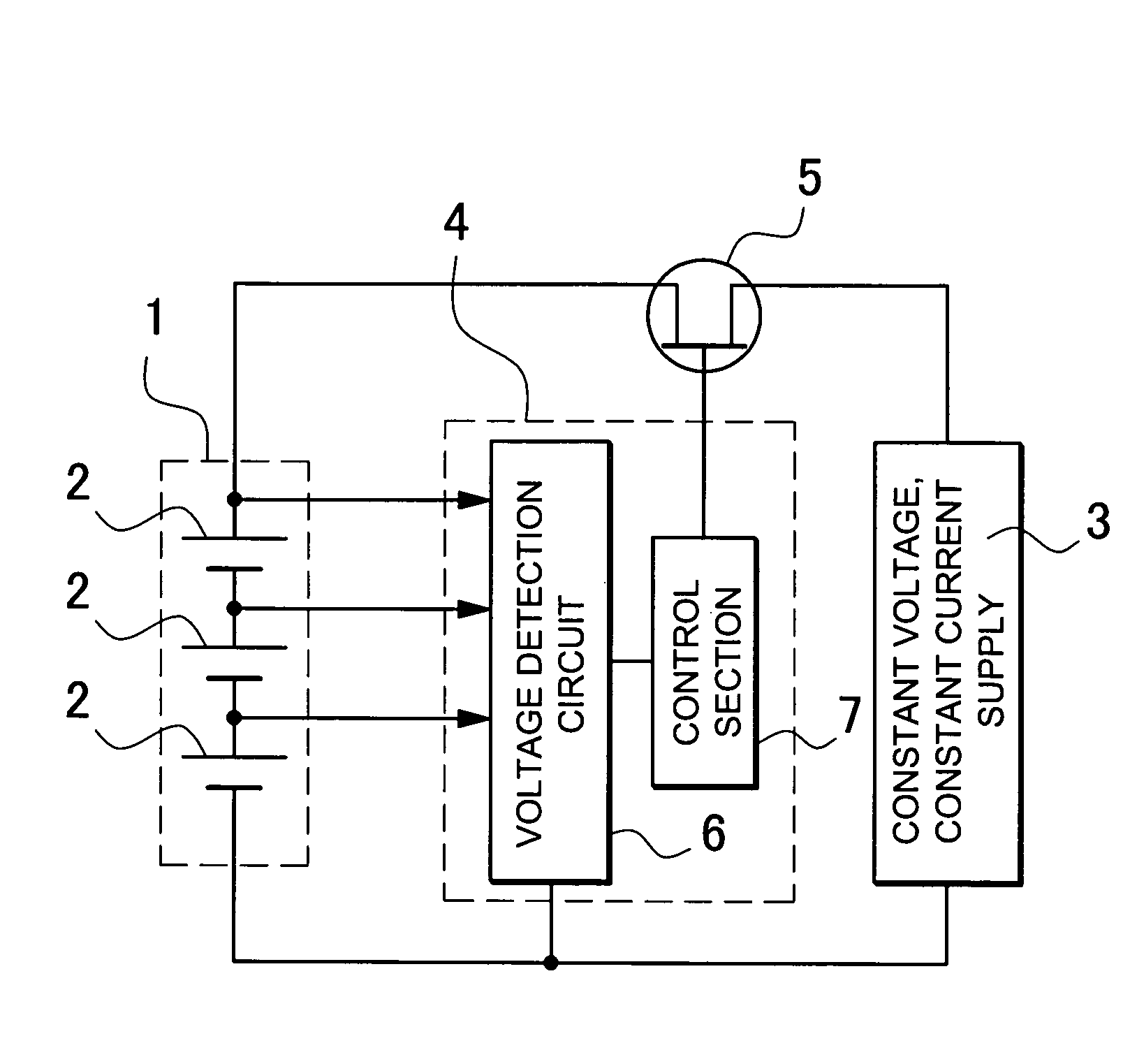
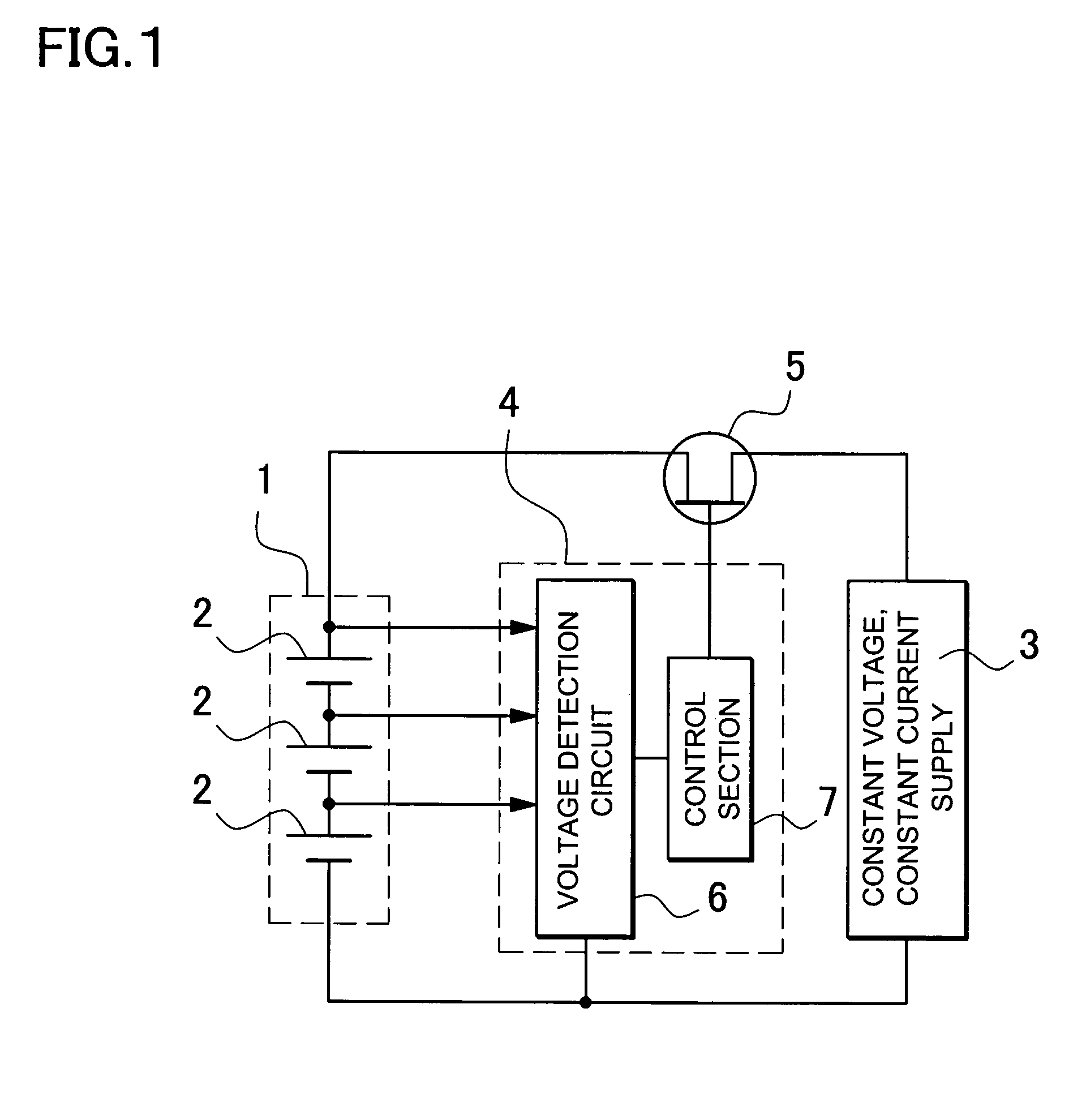
[0026]The battery pack 1 of FIG. 1 has a plurality of lithium ion rechargeable batteries 2 connected in series. This battery pack 1 is charged by a constant current, constant voltage power supply 3. The constant current, constant voltage supply 3 charges the battery pack 1 with output voltage limited below the maximum voltage and output current limited below the maximum current. For a discharged battery pack 1, total output voltage is reduced. When a discharged battery pack 1 is charged by the constant current, constant voltage supply 3, total battery pack 1 voltage is less than the maximum voltage of the power supply. Therefore, voltage is not limited but output current is limited to the maximum supply current and the battery pack 1 is charged by a constant current. As charging proceeds, total battery pack 1 voltage rises. When total battery pack 1 voltage rises to the maximum voltage of the constant current, constant voltage supply 3, voltage is limited to that maximum voltage and...


PUM


Abstract

The battery pack charging method charges a battery pack, which is a plurality of lithium ion rechargeable batteries connected in series, to full charge by constant current and constant voltage charging. Constant current charging is performed until total voltage reaches a prescribed total voltage. Subsequently, constant current charging is switched to constant voltage charging until full charge is reached. In addition, the voltage of each battery being charged is detected. When the voltage of any battery exceeds a first specified voltage, charging is switched to pulse charging.

Description

BACKGROUND OF THE INVENTION[0001]1. Field of the Invention[0002]The present invention relates to a charging method for a battery pack that is a series connection of a plurality of lithium ion rechargeable batteries, and in particular relates to a charging method that charges while protecting a particular battery when its battery voltage becomes high.[0003]2. Description of the Related Art[0004]In a lithium ion rechargeable battery pack, a plurality of batteries are connected in series to raise the output voltage. This battery pack is fully charged by charging with constant current until battery voltage reaches a specified voltage, then subsequently charging with constant voltage to avoid rise in battery voltage. Since battery pack batteries are connected in series, the same charging current flows through all the batteries. If the electrical characteristics of all the series connected batteries are the same, battery voltage will rise in the same manner in all batteries. However, as t...

Claims


Application Information

Patent Timeline
IPC IPC(8): H01M10/44
CPCH01M10/0525H01M10/441Y02E60/122H02J7/0093H02J7/0022H02J7/00711Y02E60/10H02J7/0014
Inventor KURIHARA, TOSHITAKEMORI, TATSUOSUZUKI, KATSUHIRO
Owner GK BRIDGE 1
Why Eureka
Try Eureka