Data recording evaluation method and optical disk recording and reproduction device

a data recording and evaluation method technology, applied in the field of data recording evaluation methods and optical disk recording and reproduction devices, can solve problems such as high probability of errors and techniques that have not been successful in establishing appropriate associations

Inactive Publication Date: 2008-08-28
TAIYO YUDEN KK
View PDF7 Cites 7 Cited by
  • Summary
  • Abstract
  • Description
  • Claims
  • Application Information

AI Technical Summary

Benefits of technology

[0020]A first changing step may be provided for changing a recording condition for data recording based on the second evaluation index value. Thus, a recording condition of data recording can be properly adjusted in a comprehensive manner based on the second evaluation index value.
[0023]The method according to the invention may further include a second changing step for changing a recording parameter used for data recording based on the first evaluation index values of the detection patterns identified. As a result, a recording parameter can be effectively adjusted.
[0043]The invention makes it possible to make a total evaluation of data recording by employing a novel evaluation index.

Problems solved by technology

Specifically, a calculation is carried out to obtain a reliability value |Pa−Pb|−Pstd| of the result of maximum likelihood decoding of a region which corresponds to leading and end portions of recorded marks and in which maximum likelihood decoding can result in an error at a high probability.
Although there are various techniques for evaluating data recording as described above, those techniques have not been necessarily successful in establishing appropriate association between an evaluation of data recording as a whole and an evaluation of data recording of individual recorded patterns.

Method used


Image

  • Data recording evaluation method and optical disk recording and reproduction device
  • Data recording evaluation method and optical disk recording and reproduction device
  • Data recording evaluation method and optical disk recording and reproduction device

Examples


Embodiment Construction

(1) Evaluation Index PRerror for Each Pattern

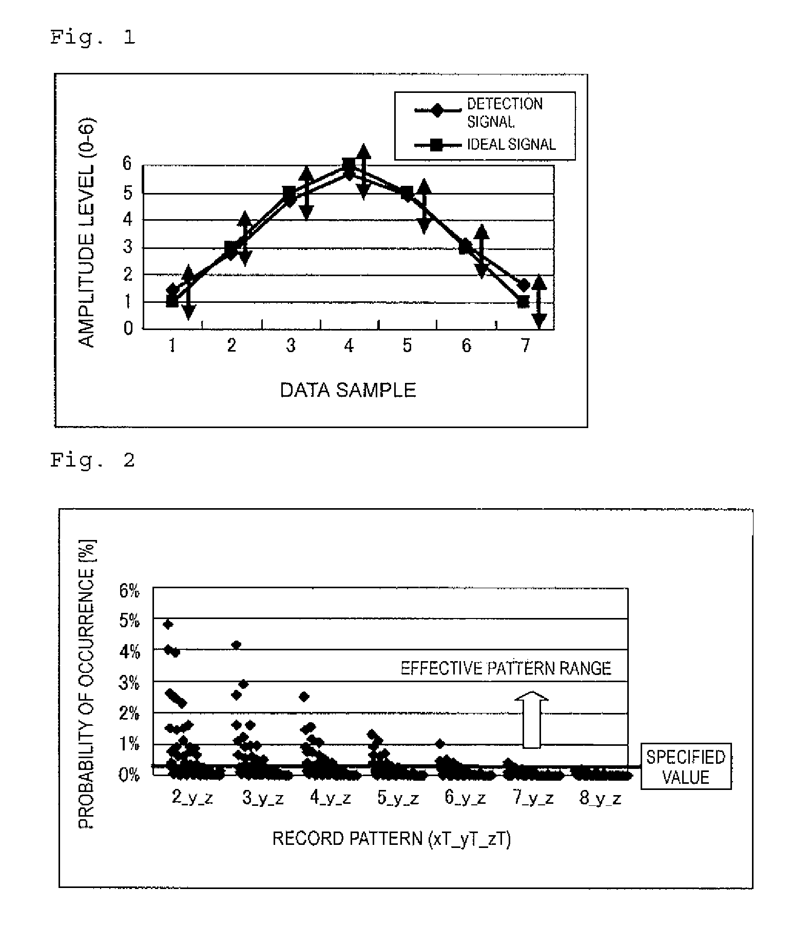
[0070]FIG. 1 shows amplitude levels read from a predetermined detection pattern which is, for example, a 4T mark (a mark having a length 4T which may be called a pit), the mark being read along with 3T spaces (spaces having a length 3T which may be called lands) provided adjacent to the same on both sides thereof. In FIG. 1, the vertical axis represents amplitude levels, and the horizontal axis represents data samples of position information of the 4T mark in the moving direction thereof, the samples being under influence of the 3T spaces adjacent to the mark. The influence of the adjacent spaces is more significant, the further the part of interest of the mark 4T from the center of the mark. When PR(1, 2, 2, 1) according to the Blu-ray standard is used, an ideal detection signal (ideal signal) or reference state of the above-described pattern has amplitude levels converted and plotted from an ideal signal obtained from profile values (1,...


PUM

PropertyMeasurementUnit
recording poweraaaaaaaaaa

Abstract

Novel evaluation indexes are introduced to allow both a total evaluation of data recording and an evaluation of individual detection patterns. A data recording evaluation method includes a step of reproducing a result of data recording performed on an optical disk and identifying a predetermined detection pattern in a reproduction signal, a step of detecting a signal state of the reproduction signal associated with the predetermined detection pattern, and a first calculation step for calculating a first evaluation index value based on the detected signal state and a reference state identified from the predetermined detection pattern. When there is a plurality of predetermined detection patterns as described above, a second calculation step is further provided for calculating a second recording state evaluation index value using the first evaluation index value calculated from each of the predetermined detection patterns. Data recording can be properly evaluated using the first and second recording state evaluation index values.

Description

BACKGROUND OF THE INVENTION[0001]1. Field of the Invention[0002]The present invention relates to a technique for evaluating recording of data on an optical disk.[0003]2. Description of the Related Art[0004]Optical disks such as write-once type Blue-ray discs (hereinafter referred to as “BD-R”) and write-once type HD-DVD discs (hereinafter referred to as “HD-DVD-R”) are constructed by forming a recording layer, a reflective layer, and a protective layer if necessary on one surface of a substrate in the form of a light-transmitting disk. Spiral or concentric grooves are formed on the surface of the substrate having a recording layer and a reflective layer formed thereon, and convex parts called lands are formed between adjoining grooves. Recording is performed on such an optical disk by irradiating the recording layer on the grooves with a recording laser beam from an optical disk recording and reproduction device so as to track the grooves with the beam, thereby forming pits on the r...

Claims


Application Information

Patent Timeline
Patent Type & Authority Applications(United States)
IPC IPC(8): G11B27/36G11B7/00
CPCG11B7/00458G11B20/10009G11B7/1267G11B7/0045G11B20/18
Inventor KAKIMOTO, HIROYAMIYAZAWA, FUYUKISEKIGUCHI, MITSUOOYAMA, KATSUHIRO
Owner TAIYO YUDEN KK
Why Eureka
Try Eureka