
Method of coding a video signal

Inactive Publication Date: 2008-08-28
GOOGLE LLC
View PDF9 Cites 1 Cited by
  • Summary
  • Abstract
  • Description
  • Claims
  • Application Information

AI Technical Summary

Benefits of technology

[0008]An object of the present invention is to provide encoding and decoding of a video sequence which improves the perceptual video quality with only a moderate increase of the bit-rate for transferring the encoded video sequence.
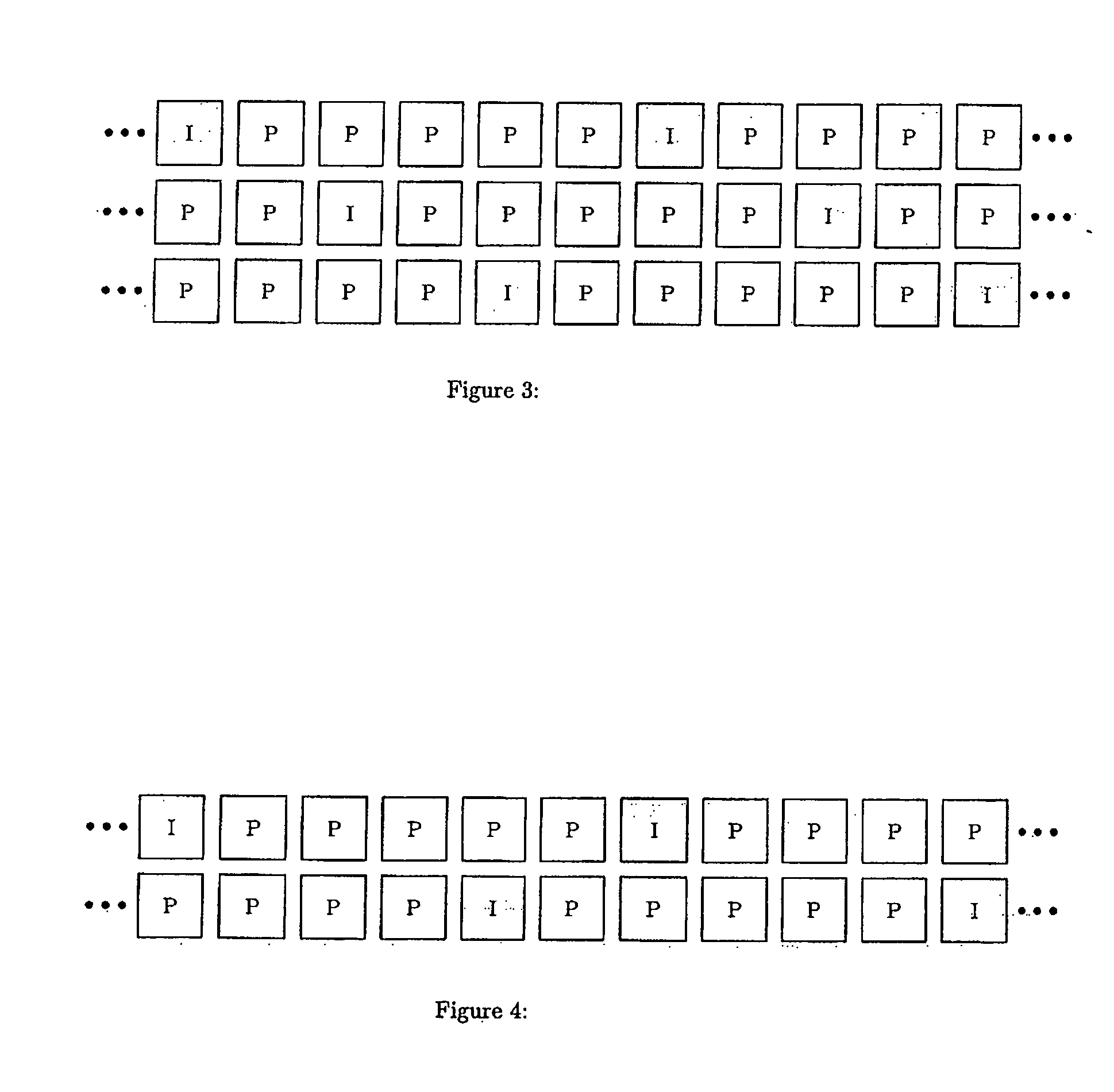
[0011]The use of more than one encoder for encoding the same video sequence has the advantage of increasing the possibility that one or more encoded descriptions of a video sequence frame are received without error, even though one or more encoded descriptions of the same frame are non-existent due to an error or delay when transferring the encoded video sequence over a network from a transmitting end to a receiving end. By displacing the encoding operations of the encoders in time, the probability that the received encoded sequences include propagated errors at the same time will be reduced. This is because the different encoded sequences will have some kind of zero states occurring at different points in time. With increased time since the last zero state for an encoded sequence, the higher probability of a propagated error for that encoded sequence. By displacing the zero states for the different encoded sequences, there will always be a lower probability of a propagated error for one or more of the sequences than for the other(s). In comparison, with no displacement of the zero states for the encoded sequences, all encoded sequences will simultaneously increase their probability of including a propagated error up to the point when, at the same time for all sequences, new encoded zero states occur.
[0012]Another advantage of displacing the encoding operations of the encoders in time is achieved in case of a disruption in the network transferring all the encoded video sequences and effecting all the sequences at the same time. In such case, the time until one of the video sequences includes a zero state after the disruption will in most cases be smaller, as compared to the case with no displacement of the zero state. In the latter case, since the zero states for the multiple encoded sequences occur simultaneously, the time to the next zero state for all the multiple encoded sequences will be the same as in the case when only one single encoded sequence is used for transferring the video.
[0016]Thus, it will be appreciated that the present invention provides video sequence encoding using two or more encoders such that shorter error propagation on an average is provided, which results in perceptually improved quality of the displayed video at a receiving end after decoding of the video sequences. In addition, it will be appreciated that displacing the encoding operations for different encoders in time does not increase the bit-rate for transferring the different encoded video sequences, as compared to transferring the same number of encoded video sequences without any displacement of the encoding operations. Thus, the present invention improves the video quality by ensuring robustness against transmission errors.

Problems solved by technology

This strict requirement makes the overall number of errors in transmission increase, since delayed packets are handled equivalently to lost packets.
Existing video coding techniques, using the mentioned setup with different frame types, are not suitable for live video communication due to the strict delay restriction.
Introducing high dependency between frames to achieve a bit-efficient representation of the signal results in display of erroneous video in environments where the probability of transmission error is significant.
Not only is it impossible to render frames that are not received in time, but the frame dependency makes the error propagate throughout the video sequence, which is annoying to the viewer.

Method used


Image

  • Method of coding a video signal
  • Method of coding a video signal
  • Method of coding a video signal

Examples


Embodiment Construction

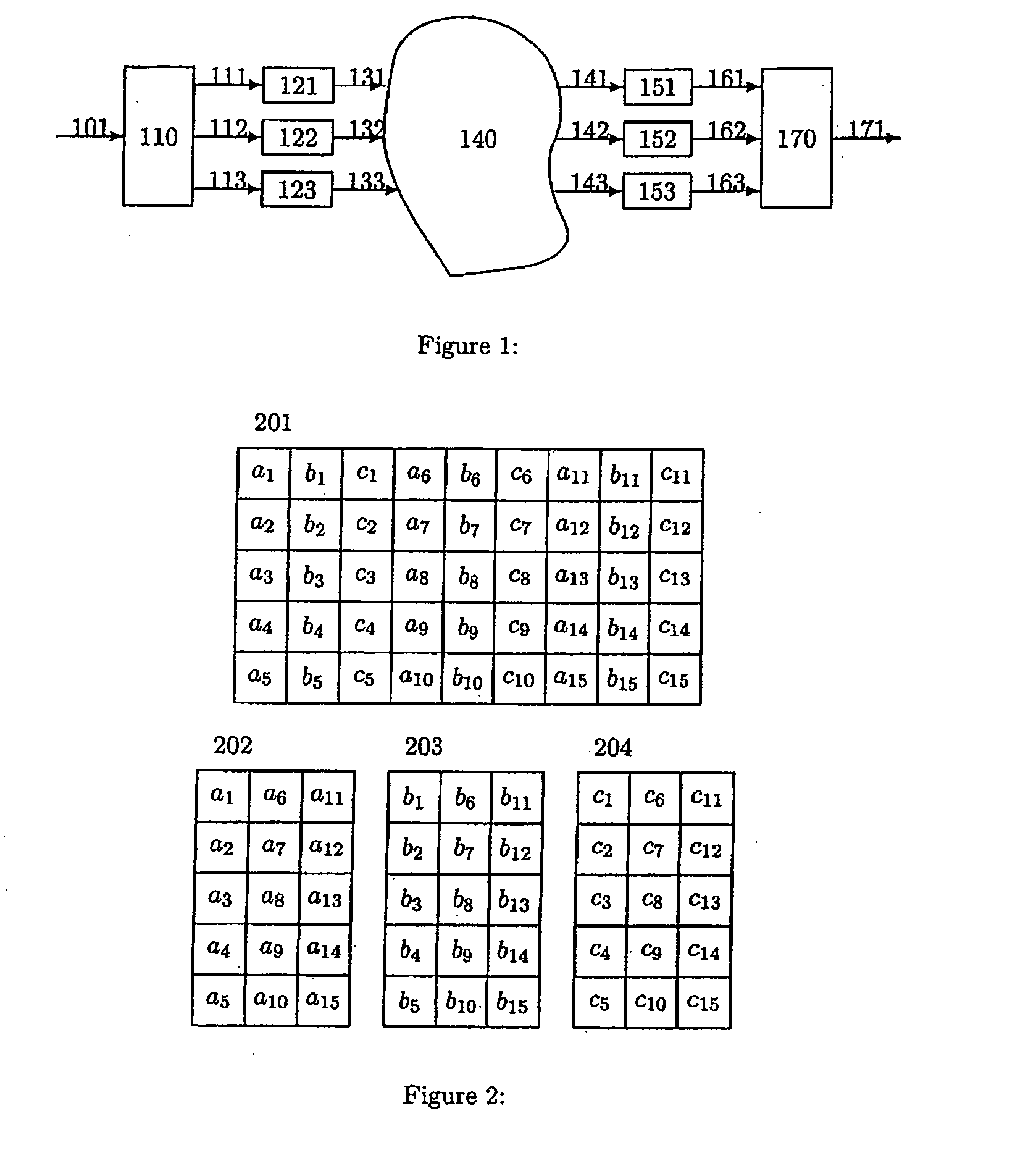
[0024]FIG. 1 schematically shows an exemplifying overall system environment in which the different embodiments of the invention may be included and arranged to operate.

[0025]In FIG. 1 a digitized video signal 101, divided into frames, is input, each frame representing a still image in time.

[0026]In general, to obtain robustness to transmission errors, a video signal can be divided into multiple descriptions. Each description is then encoded in a separate coding unit which is an implementation of an existing standard coder. This implies that there are I-frames and P-frames for each description. In case all descriptions are received at the receiver end, the best quality of video is obtained. In case there are errors in the transmission, affecting a number of descriptions, these descriptions are disregarded until they have been updated by an I-frame. Of course, this has the effect that the quality of the video is reduced temporarily.

[0027]The descriptions in a multiple description vide...


PUM


Abstract

The invention relates to methods and apparatuses for encoding and decoding of a video sequence. In connection with encoding / decoding a video sequence it is desirable to increase the video quality without having to increase the bit-rate for the encoded video too much, thereby still providing a bit-efficient representation of the video. If multiple descriptions of the video sequence is used the invention improves the video quality without any increase of the bit-rate. According to the invention, this is achieved by using two or more coding units for encoding the same video sequence, wherein the encoding units perform their encoding operations displaced in time in relation to each other. Correspondingly, two or more decoding units are used for decoding the same video sequence, wherein the decoding units perform their decoding operations displaced in time in relation to each other.

Description

TECHNICAL FIELD OF THE INVENTION[0001]The present invention relates to a method and apparatus for encoding of a video sequence.BACKGROUND OF THE INVENTION[0002]A video sequence consists of a number of still images called frames. Coding of a video sequence, video coding, is done by describing the frames as bit-efficiently as possible. To do this, redundancy in the video sequence is exploited. There are three types of redundancies that can be exploited, temporal redundancy, spatial redundancy and spectral redundancy. Temporal redundancy is the redundancy between two frames, while spatial redundancy is the redundancy within a frame. Spectral redundancy is the redundancy between different colour components in the video. In the following we will not consider the spectral redundancy.[0003]Video coding standards define a number of frame types, out of which the I-frame and the P-frame are common to most standards. The I-frame is coded by exploiting spatial redundancy solely, resulting in a ...

Claims


Application Information

Patent Timeline
IPC IPC(8): H04N7/32
CPCH04N21/23439H04N21/26275H04N21/4305H04N19/136H04N19/61H04N19/12H04N19/46H04N19/172H04N19/44
Inventor KOZICA, ERMINZACHARIAH, DAVEKLEIJN, WILLEM BASTIAAN
Owner GOOGLE LLC
Learn More