Structural light based depth imaging method and system using signal separation coding, and error correction thereof

a three-dimensional depth imaging and structural light technology, applied in the field of three-dimensional depth imaging methods and systems, can solve the problems of code indexes that cannot correct the mixing of signals sent from a far place, disadvantages of obtaining three-dimensional information in a complex environment, and light distortion

Active Publication Date: 2008-08-28
RES & BUSINESS FOUND SUNGKYUNKWAN UNIV
View PDF3 Cites 56 Cited by
  • Summary
  • Abstract
  • Description
  • Claims
  • Application Information

AI Technical Summary

Benefits of technology

[0025]Another aspect of the invention provides a depth imaging system comprising projection apparatus for radiating light onto an object to be measured, image photographing apparatus for photographing the light radiated from the projection means, and processing means for measuring a three-dimensional depth image of the object wherein the processing means detects, removes or corrects an error of a corresponding point between a projection apparatus and an image photographing apparatus caused by a phenomenon including reflection and blur using geometrical constraints between the projection apparatus and the image photographing apparatus.

Problems solved by technology

Hereinafter, the temporal coding method will be described, except the spatial coding method and the hybrid coding method, which are disadvantageous to obtain three-dimensional information in complex environment.
However, it is impossible for the code index to correct mixing of signals sent from a far place.
Since the structural light system is a system of projecting light to obtain three-dimensional information, distortion of light may be a major cause of the error.
When reflection, focus error, interference of external light, interface, and temporal code are used, motion of the object (when the temporal code is used) during projection of the pattern may also become a factor of the error.
The errors generated due to reflection, affection of external factors, and mixing of signals cause a large pixel-wise error.
However, a research for basically solving the problems has not been performed.

Method used


Image

  • Structural light based depth imaging method and system using signal separation coding, and error correction thereof
  • Structural light based depth imaging method and system using signal separation coding, and error correction thereof
  • Structural light based depth imaging method and system using signal separation coding, and error correction thereof

Examples


Embodiment Construction

[0042]Hereinafter, exemplary embodiments of the present invention will be described with reference to the accompanying drawings.

[0043]The present invention provides a two-dimensional temporal code and multi-camera based depth imaging method in order to correct an error generated a structural light system.

[0044][Two-Dimensional Code]

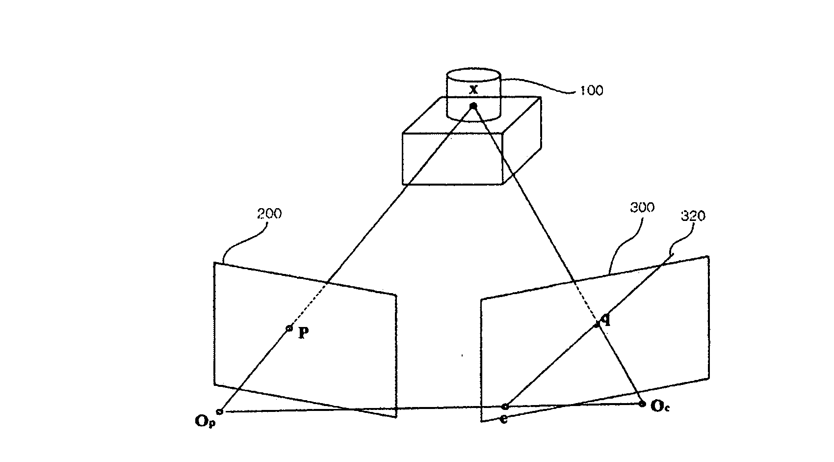
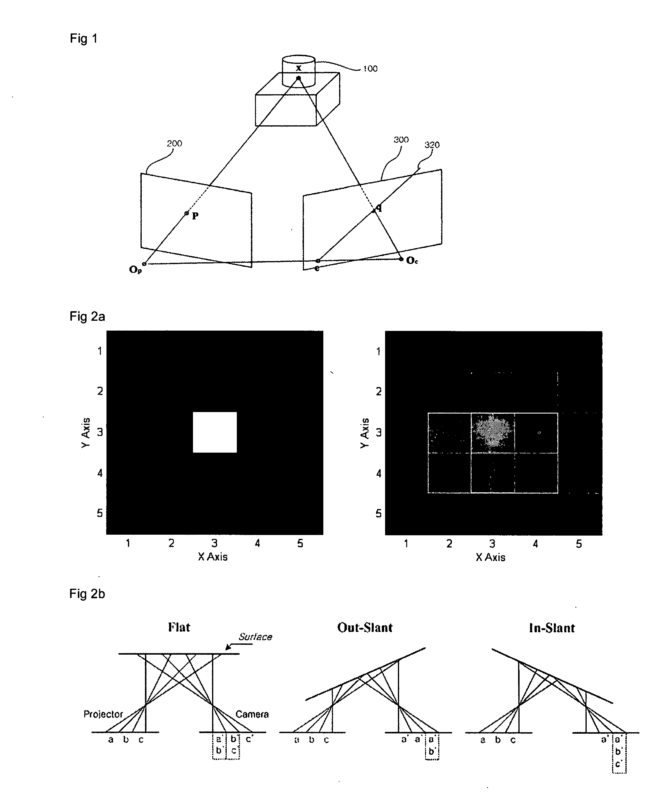
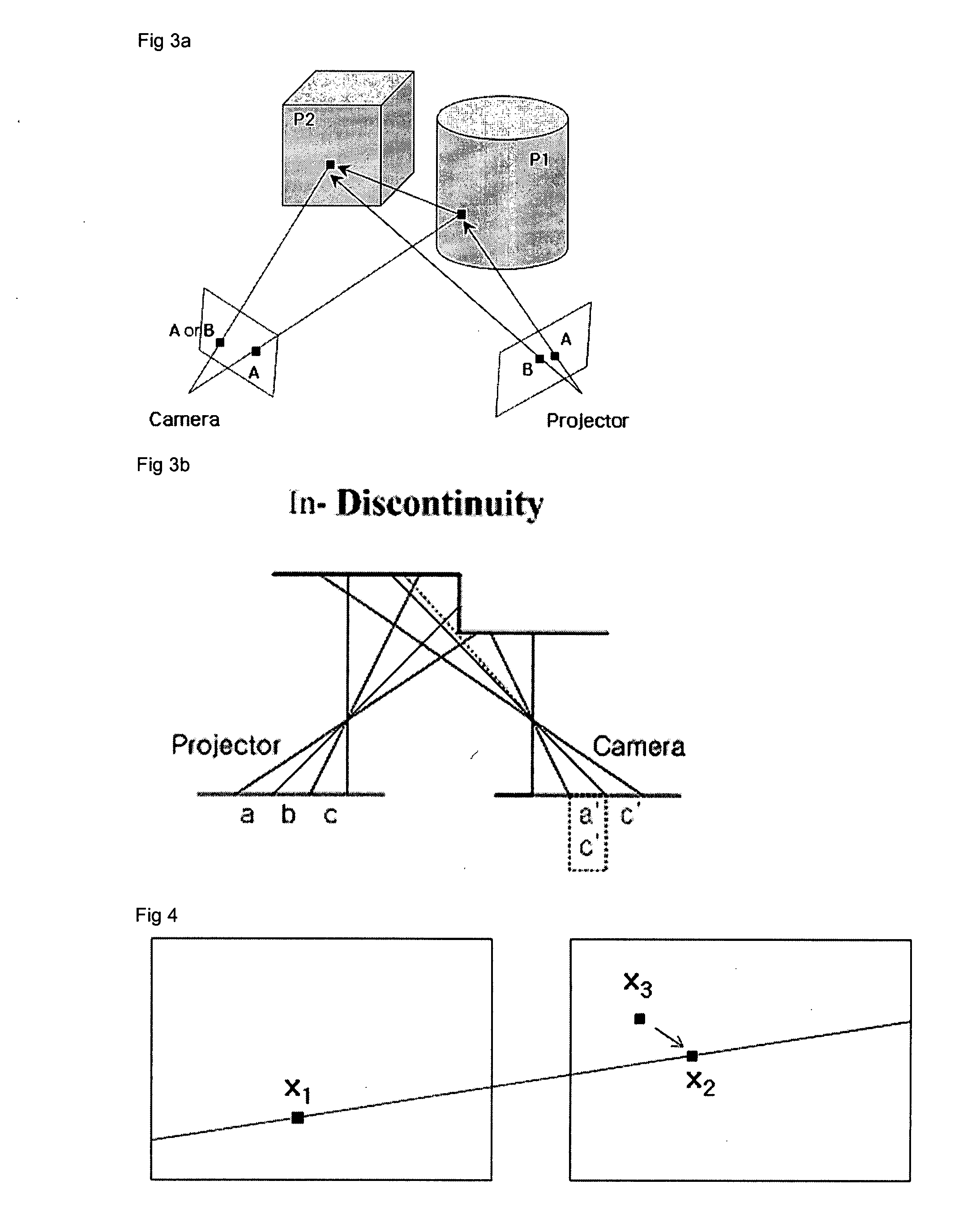
[0045]A two-dimensional temporal code means a method of encoding the entire space into a plurality of images. Since several conventional methods of encoding the entire space using a single dimensional code cannot use an epipolar geometry, it is impossible to determine existence of an error caused by reflection of an object surface. However, using a two-dimensional code, it is possible to detect and correct an error using epipolar constraints. Addresses, which are incorrectly estimated due to the reflection, may produce a three-dimensional value, not existing on an object surface or in a region hidden by another object, i.e., a shadow region.

[0046]As shown...


PUM


Abstract

Provided is a structural light based three-dimensional depth imaging method and system using signal separation coding and error correction thereof capable of detecting, removing and correcting corresponding errors between a projection apparatus and an image photographing apparatus caused by phenomena such as reflection on an object surface, blurring by a focus, and so on, using geometrical constraints between the projection apparatus and the image photographing apparatus. Here, the projection apparatus projects light, and the image photographing apparatus obtains the light. The depth imaging method includes projecting light from a projection apparatus, obtaining the light using an image photographing apparatus, and measuring a distance or a three-dimensional depth image. Therefore, it is possible to provide a structural light based thee-dimensional depth imaging method and system using geometrical conditions capable of precisely obtaining three-dimensional depth information of target environment.

Description

CROSS-REFERENCE TO RELATED APPLICATION[0001]This application claims the benefit of Korean Patent Applications No. 10-2007-0020080, filed on Feb. 28, 2007, and No. 10-2007-0026811, filed on Mar. 19, 2007, which are fully incorporated by reference in their entireties.BACKGROUND OF THE INVENTION[0002]1. Field of the invention[0003]The present invention relates to a three-dimensional depth imaging method and system, and more particularly, to a structural light based three-dimensional depth imaging method and system using signal separation coding capable of detecting, removing and correcting corresponding errors between a projection apparatus and an imaging apparatus caused by phenomena such as reflections on an object surface, blurring by a focus, and so on, using geometrical constraints between the projection apparatus and the imaging apparatus. Here, the projection apparatus projects light and the imaging apparatus obtains the light.[0004]2. Description of the Prior Art[0005]Generally...

Claims


Application Information

Patent Timeline
Patent Type & Authority Applications(United States)
IPC IPC(8): G06K9/03
CPCG01B11/25
Inventor LEE, SUK-HANCHOI, JONG-MOOKIM, DAE-SIKOH, SEUNG-SUB
Owner RES & BUSINESS FOUND SUNGKYUNKWAN UNIV
Why Eureka
Try Eureka