Eureka AIR delivers breakthrough ideas for toughest innovation challenges, trusted by R&D personnel around the world.

Image forming apparatus and developing device thereof

Inactive Publication Date: 2008-08-28
S PRINTING SOLUTION CO LTD
View PDF2 Cites 6 Cited by
  • Summary
  • Abstract
  • Description
  • Claims
  • Application Information

AI Technical Summary

Benefits of technology

[0013]Accordingly, the present general inventive concept provides an image forming apparatus and a developing device that can efficiently utilize an inner space of the apparatus by improving the construction and the mounting structure of a device to charge paper.
[0014]The present general inventive concept also provides an image forming apparatus and a developing device thereof that prevents deterioration of image quality due to an excessive pressure exerted on paper during the paper charge function.

Problems solved by technology

However, the paper attaching roller 4 is only installed in one of the spaces SY, SM, SC, and SK formed among the developing devices, and thus the remaining unused spaces are superfluous.
But, the spaces SM, SC, and SK, which are formed between the paper feed belt 3 and the other developing devices 1M, 1C and 1K, create an unnecessary waste of space.
The inconsistent feeding speed of the paper causes deterioration of image quality, e.g., color discordance.
Further, as the image forming apparatus is used over a long period of time, paper dust or residual toner particles accumulate inside of the image forming apparatus during the developing process.
Thus, another drawback of the conventional image forming apparatus is that the outer peripheral surface of the paper attaching roller 4 is easily contaminated with dust from the paper P dust or toner particles.

Method used


Image

  • Image forming apparatus and developing device thereof
  • Image forming apparatus and developing device thereof
  • Image forming apparatus and developing device thereof

Examples


Embodiment Construction

[0044]Reference will now be made in detail to embodiments of the present general inventive concept, examples of which are illustrated in the accompanying drawings, wherein like reference numerals refer to like elements throughout. The embodiments are described below to explain the present general inventive concept by referring to the figures.

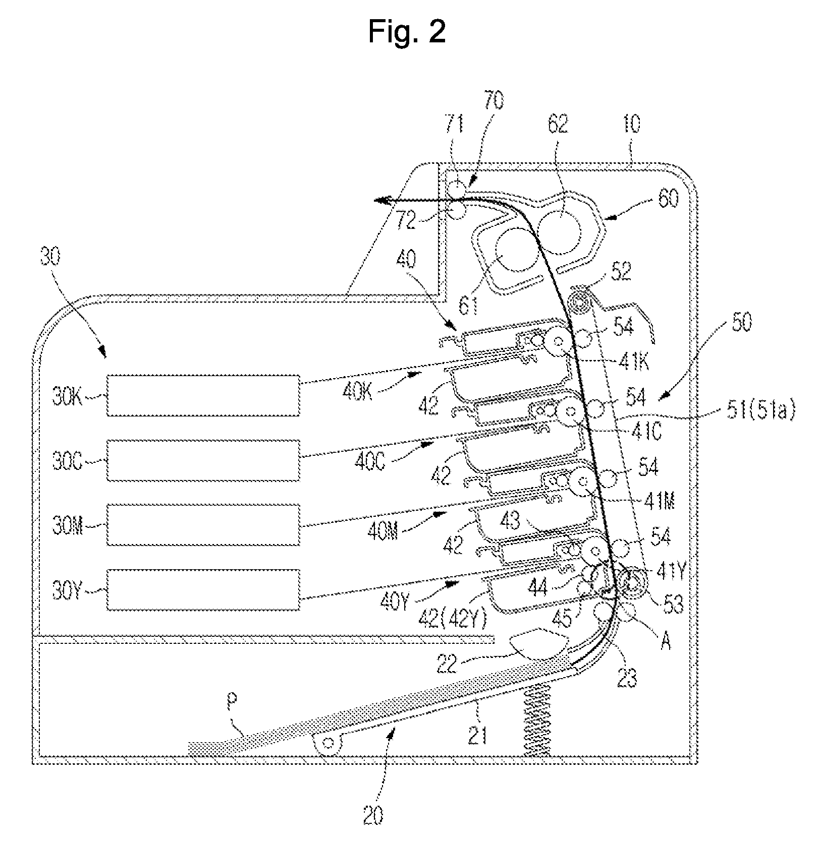
[0045]FIG. 2 is a sectional view illustrating the image forming apparatus in accordance with an embodiment of the present general inventive concept.

[0046]As illustrated in FIG. 2, the image forming apparatus according to the present embodiment includes a main body 10, which forms an external housing and supports components installed inside the image forming apparatus, a paper supply unit 20, an exposure unit 30, a development unit 40, a transfer unit 50, a fixing unit 60, and a paper discharge unit 70.

[0047]The paper supply unit 20 supplies a printing medium, e.g., paper P, to the image forming apparatus. The paper supply unit 20 includes a pape...


PUM

PropertyMeasurementUnit
Thicknessaaaaaaaaaa
Electrical conductoraaaaaaaaaa
Electric potential / voltageaaaaaaaaaa

Abstract

An image forming apparatus having the improved construction and mounting structure of a device for charging paper to be attached to a paper feed body is disclosed. The image forming apparatus includes a plurality of developing devices and a paper feed body which is mounted opposite to the plurality of developing devices and rotates to feed paper. A sheet member is mounted to a developing device of the plurality of developing devices, which is disposed on an uppermost paper stream side in a feeding direction of the paper. The sheet member charges the paper as it advances to the paper feed body to attach the paper to the paper feed body. The image forming apparatus further includes a voltage transmission part which transmits high voltage to the sheet member. The voltage transmission part includes a conductive fixing member to which an end of the sheet member is fixed, and a voltage transmission plate having a first end portion with a terminal contact portion to contact a terminal mounted in a main body and a second end portion electrically connected to the fixing member.

Description

CROSS-REFERENCE TO RELATED APPLICATIONS[0001]This application claims the benefit under 35 U.S.C. 119 (a) of Korean Patent Application No. 2007-0018525, filed on Feb. 23, 2007 in the Korean Intellectual Property Office, the disclosure of which is incorporated in its entirety.BACKGROUND OF THE INVENTION[0002]1. Field of the Invention[0003]The present general inventive concept relates to an image forming apparatus, and more particularly to an image forming apparatus in which paper is fed while being attached to a paper feed body.[0004]2. Description of the Related Art[0005]An image forming apparatus is an apparatus that prints an image on a printing medium, e.g., paper, according to an inputted image signal. One example of the image forming apparatus is an electrophotographic image forming apparatus. The electrophotographic image forming apparatus is configured such that a light beam is scanned across a photosensitive body charged with a predetermined electric potential to form an elec...

Claims


Application Information

Patent Timeline
IPC IPC(8): G03G15/01
CPCB65H5/021B65H2301/5132G03G15/6588G03G15/0233B65H2801/06G03G15/0121
Inventor KIM, JONG INBAEK, MYOUNG SU
Owner S PRINTING SOLUTION CO LTD
Why Eureka
Eureka Blog
Learn More