Method of Making Fiber Optic Couplers with Precise Postioning of Fibers

Inactive Publication Date: 2008-09-04
TREMBLAY JULIEN
View PDF9 Cites 32 Cited by
  • Summary
  • Abstract
  • Description
  • Claims
  • Application Information

AI Technical Summary

Benefits of technology

[0005]It is an object of the present invention to provide a simple and efficient method of making couplers, such as 1×N or N×1, by

Problems solved by technology

This is not always easy to achieve.
The above described arrangements have many disadvantages since they require preforms with r

Method used


Image

  • Method of Making Fiber Optic Couplers with Precise Postioning of Fibers
  • Method of Making Fiber Optic Couplers with Precise Postioning of Fibers
  • Method of Making Fiber Optic Couplers with Precise Postioning of Fibers

Examples


Embodiment Construction

[0034]The invention will now be described by way of preferred non-limitative embodiments, with reference to the appended drawings in which the same elements are designated by the same reference numbers.

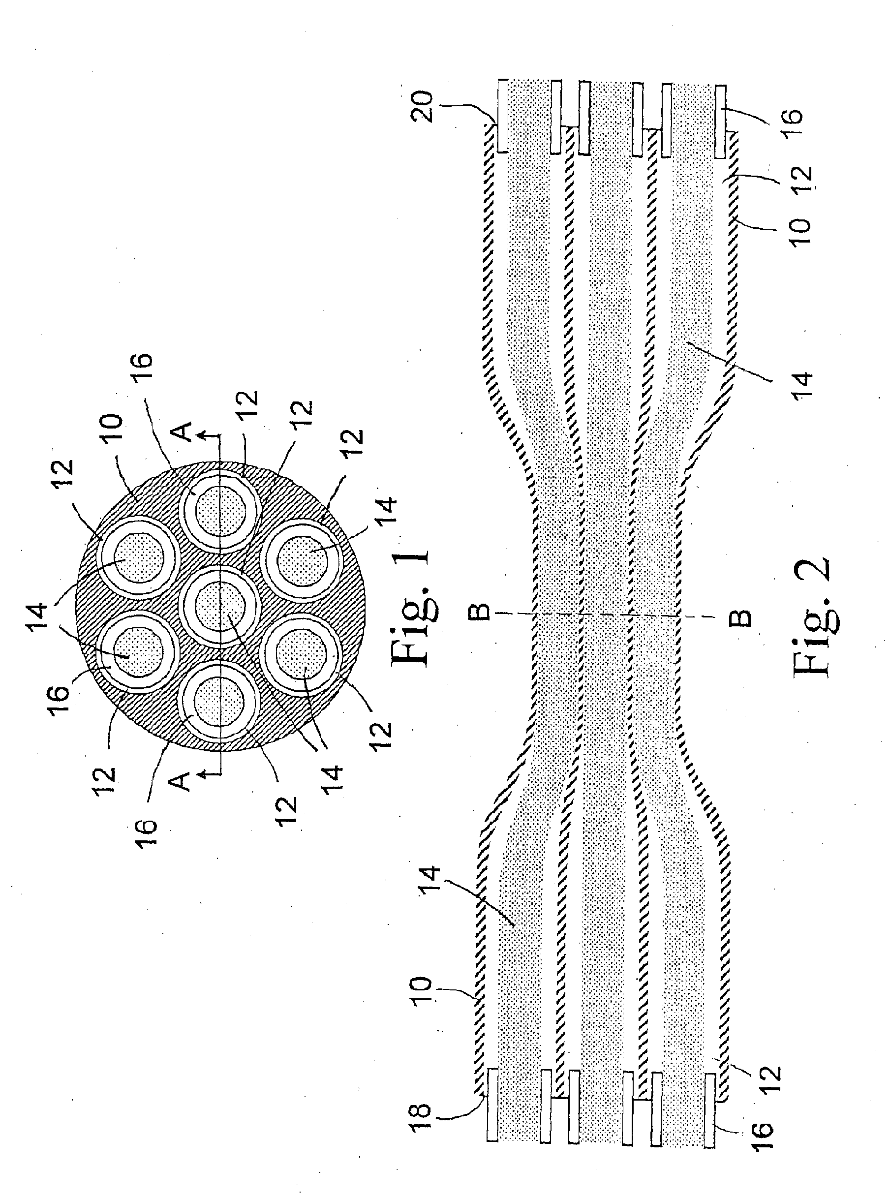
[0035]FIG. 1 illustrates one embodiment of the present invention in which a circular glass preform 10 is provided, in which capillary holes 12 are formed in a predetermined disposition. In the present case, all holes are of the same size and are symmetrically disposed with one hole being in the middle, surrounded by six holes around the middle one. These holes are slightly larger than the coated optical fibers 14 that are inserted therein. The fibers 14 have a coating 16 surrounding each fiber 14.

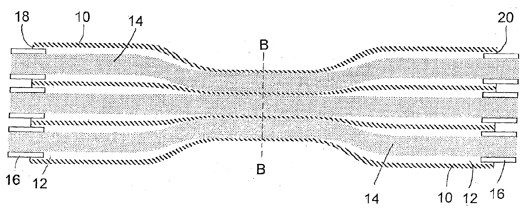
[0036]FIG. 2 shows a longitudinal cross-sectional view along line A-A of FIG. 1. Initially, the preform 10 has a diameter shown at either end of FIG. 2. Fibers 14 are inserted into this preform 10 after removal of the coating 16. The insertion is preferably done so that the coated ends of the...


PUM

PropertyMeasurementUnit
Shapeaaaaaaaaaa
Tensionaaaaaaaaaa

Abstract

The method uses capillary holes in a glass preform for precise positioning of the optical fibers in the manufacture of a coupler. The glass preform is preferably cylindrical and longitudinal capillary holes are made in it in a desired pattern. Optical fibers are inserted in the holes and the glass preform is heated and stretched in its middle section so that the fibers, from which coating has been removed, contact and are fused with the glass preform in this tapered section. Then the tapered section is cleaved to form a coupling end which is spliced with another fiber to form the coupler.

Description

FIELD OF THE INVENTION[0001]The invention generally relates to optical fiber couplers. More particularly, it relates to manufacturing of couplers with multiple fibers, such as 1×N or N×1, wherein the fibers are precisely positioned in the coupling bundle N. The invention also includes the method for making such coupling bundle with precisely positioned fibers.BACKGROUND OF THE INVENTION[0002]Various types of couplers that use bundles of fibers to be coupled, hold such fibers in the bundle either mechanically or by twisting them together, and the structure is fused and / or tapered in order to induce coupling between the fibers. For example, applicant's Canadian patent application No. 2,441,918 and its corresponding U.S. application published under No. 2005 / 0094952 A1, discloses a coupler arrangement where a bundle of a plurality of multimode fibers having a few mode fiber in the middle is fused and possibly tapered at its output end and then this output end is aligned and spliced with...

Claims


Application Information

Patent Timeline
IPC IPC(8): C03B37/00
CPCG02B6/2835G02B6/2551
Inventor TREMBLAY, JULIEN
Owner TREMBLAY JULIEN
Why Eureka
Try Eureka