Downhole Safety Valve Apparatus and Method

a safety valve and subsurface technology, applied in the direction of wellbore/well accessories, fluid removal, construction, etc., can solve the problems of obstructing the functioning and affecting the safety of the safety valv

Active Publication Date: 2008-09-04
BAKER HUGHES INC
View PDF7 Cites 18 Cited by
  • Summary
  • Abstract
  • Description
  • Claims
  • Application Information

AI Technical Summary

Benefits of technology

[0010]The deficiencies of the prior art are addressed by a safety valve retained in a bore between a first zone and a second zone. The bore can be a string of production tubing, casing, or an uncased borehole. The safety valve preferably includes an anchor assembly adaptable to retain the safety valve in the bore, and a flapper pivotably operable between an open and a closed position wherein the flapper hydraulically isolates the second zone from the first zone when in a closed position. The second zone can be a production zone. The first zone can be in communication with a surface location. The first zone can be a second production zone. In another embodiment of the invention, the anchor assembly comprises a packer element configured to sealingly engage the bore. In a further embodiment, an anchor assembly can include slips to retain the safety valve in the bore. The slips can be engaged by inclined planes. The slips can be engaged hydraulically, mechanically, electrically, or with a stored energy device. The slips can include a ratchet profile adaptable to maintain the slips in an engaged position.
[0011]The safety valve also preferably includes a mandrel having an unobstructed clearance passage wherein the mandrel is configured to slidably engage the flapper into the open position when actuated. Optionally, the safety valve can include a bypass conduit configured to permit communication between the first and the second zone when the flapper is open or closed. The bypass conduit can be a hydraulic tube. The bypass conduit can comprise a check valve on the bypass conduit to prevent fluidic communication from the second zone to the first zone. The check valve can be located anywhere on the bypass conduit. For example, the check valve can be located at the distal end of the conduit in the well bore; or, alternatively, the check valve can be located at or immediately below the safety valve body or fashioned in the body of the safety valve, all without departing from the spirit of the present invention. The bypass conduit can include an electrical cable or an optical fiber. The bypass conduit can comprise one or more communication ports through the safety valve. The ability to pass tools past the safety valve is highly desirable. The cross-sectional area of the clearance passage can be greater than 25% of the cross-sectional area of the bore. It is generally desirable that the cross-sectional area of the clearance passage can be greater than 50% of the cross-sectional area of the bore
[0012]The deficiencies of the prior art are also addressed by a downhole packer configured to

Problems solved by technology

Absent safety valves, sudden increases in downhole pressure can lead to catastrophic blowouts of production and other fluids into the atmosphere.
While the advantages of flapper-type safety valves are numerous, several drawbacks associated with their installation and use are also present.
Previously, apparatuses and methods to install a safety valve to or in existing tubing strings or wellbores accomplished the task at the expense of obstructing the passage of fluids and tools therethrough.
Another disadvantage of existing safety valve systems is that after th

Method used


Image

  • Downhole Safety Valve Apparatus and Method
  • Downhole Safety Valve Apparatus and Method

Examples


Embodiment Construction

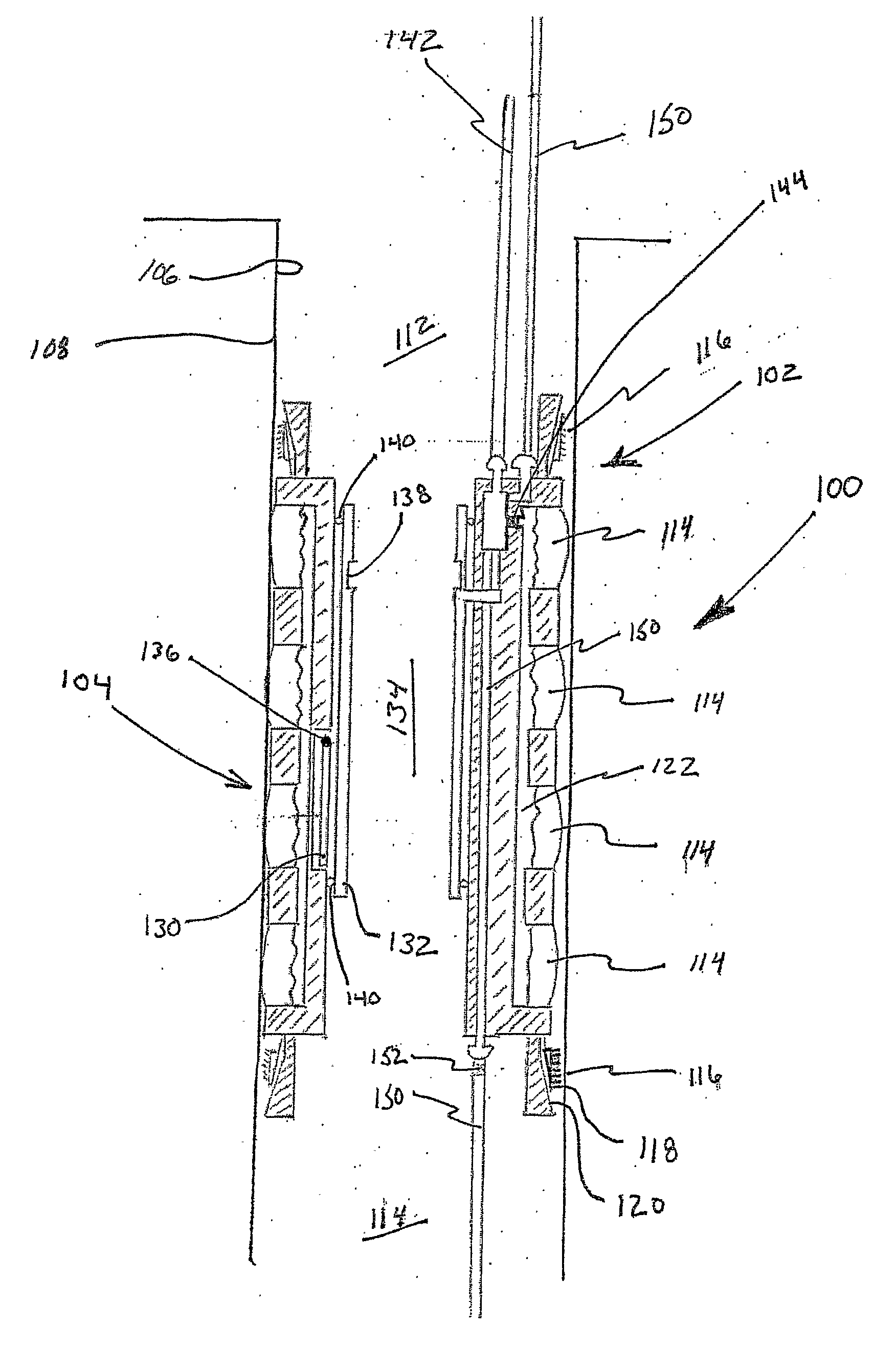
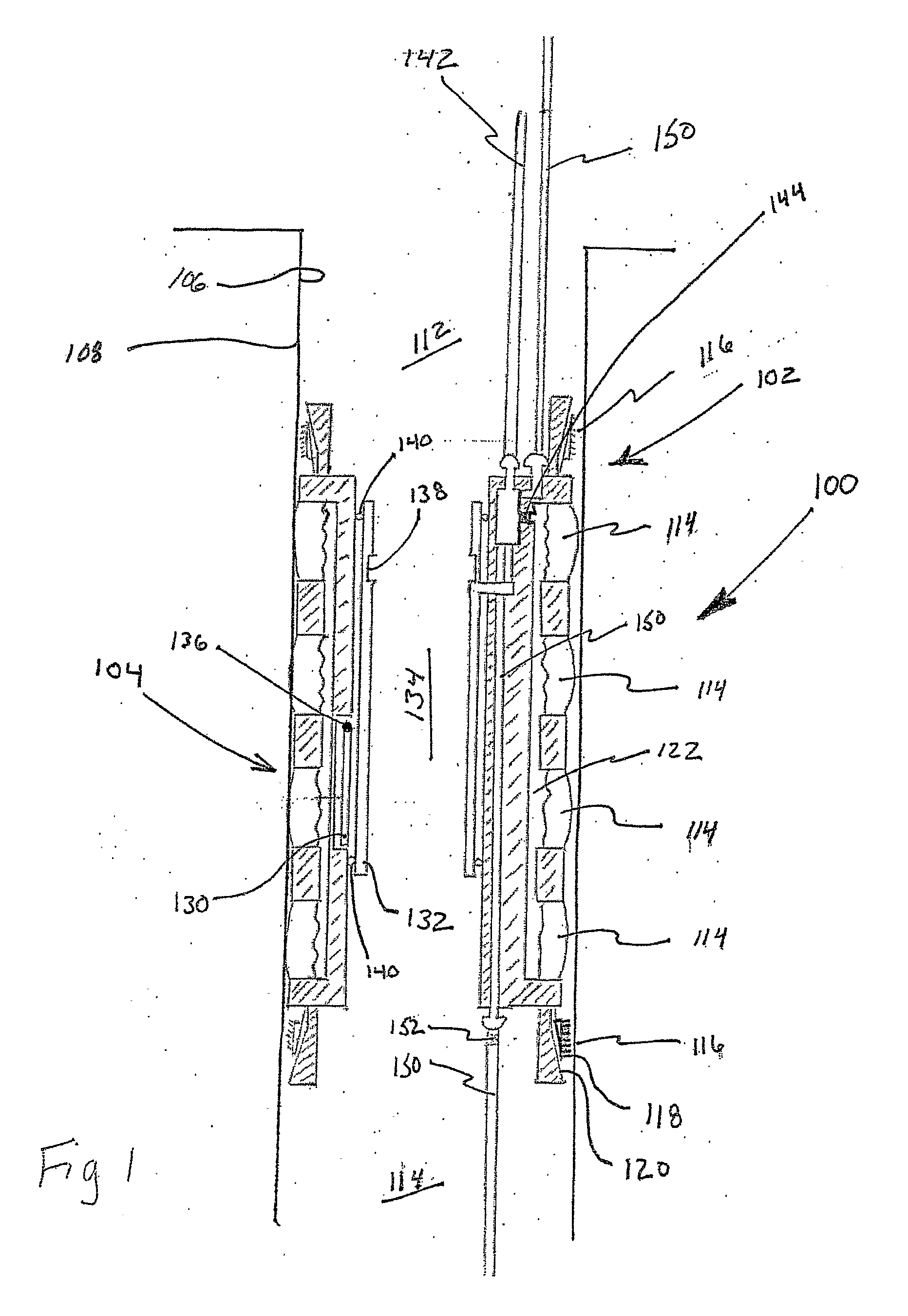
[0016]Referring to FIG. 1, an embodiment for a safety packer 100 is shown. Safety packer 100 includes an anchor subassembly 102 and a safety valve subassembly 104 disposed within an inner bore 106 of a length of tubing 108 to selectively isolate a first zone 110 from a second zone 112. While safety packer 100 is expected to be used primarily within strings of production tubing, it should be understood by one of ordinary skill in the art that safety packer assembly 100 may be used with open wellbores, casing, coiled tubing, or any other application where a packer having an integral safety valve is desirable.

[0017]Anchor subassembly 102 preferably includes a packer element 114 and at least one set of anchor slips 116 to hold safety packer 100 in place within bore 106. Safety packer 100 is configured to be placed and actuated by any means known to one skilled in the art. In one mode, anchor slips 116 having biting surfaces 118 which are engaged into bore 106 by inclined planes 120 such...


PUM


Abstract

The application discloses a safety valve including a flapper valve and a packer assembly to be installed in a bore to isolate a first zone from a second zone. Preferably, the safety valve includes a hydraulic conduit bypassing the flapper valve to allow communication therethrough when the valve is closed. Furthermore, the safety valve preferably allows unobstructed passage of tools and fluids therethrough when the flapper valve is open. The application discloses a method to install a safety valve in an existing string of tubing by deploying a packer assembly having an integral safety valve.

Description

CROSS REFERENCE TO RELATED APPLICATION[0001]This application claims the benefit of provisional application U.S. Ser. No. 60 / 522,360 filed Sep. 20, 2004.BACKGROUND OF THE INVENTION[0002]The present invention generally relates to subsurface safety valves. More particularly, the present invention relates to a packer with an integral subsurface safety valve to be deployed to a subsurface location. More particularly still, the present invention relates to a packer having a conduit configured to bypass an integral safety valve housed therein.[0003]Subsurface safety valves are typically installed in strings of tubing deployed to subterranean wellbores to prevent the escape of fluids, from one downhole zone to another. These zones can be production zones, investigation zones, intermediate zones, or upper zones in communication with the surface. Subsurface safety valves are most often used to prevent the escape of fluids from production zones to the surface, but can also be used to prevent f...

Claims


Application Information

Patent Timeline
IPC IPC(8): E21B23/01
CPCE21B33/1285E21B2034/005E21B34/105E21B2200/05
Inventor BOLDING, JEFFREY L.SMITH, DAVID R.
Owner BAKER HUGHES INC
Why Eureka
Try Eureka