
Apparatus for holding wire harness

a technology for flexibly holding and wire harnesses, which is applied in the direction of machine supports, transportation and packaging, and other domestic objects, can solve the problems of increased manufacturing cost, large size, and high cost structure, and achieve the effect of high endurance of wire harnesses and low manufacturing cos

Inactive Publication Date: 2008-09-04
YAZAKI CORP
View PDF2 Cites 23 Cited by
  • Summary
  • Abstract
  • Description
  • Claims
  • Application Information

AI Technical Summary

Benefits of technology

[0019]An object of the present invention is to provide an apparatus for holding a wire harness, the apparatus including a short wire harness and providing high endurance of the wire harness with low manufacturing cost.

Problems solved by technology

The apparatus 50 utilizes the expensive leaf spring 44, resulting in increase cost of manufacturing.
The wire harness 43 is flexibly arranged along the leaf spring 44 and thus the length thereof becomes long, resulting in a large size and high cost structure.

Method used


Image

  • Apparatus for holding wire harness
  • Apparatus for holding wire harness
  • Apparatus for holding wire harness

Examples


Embodiment Construction

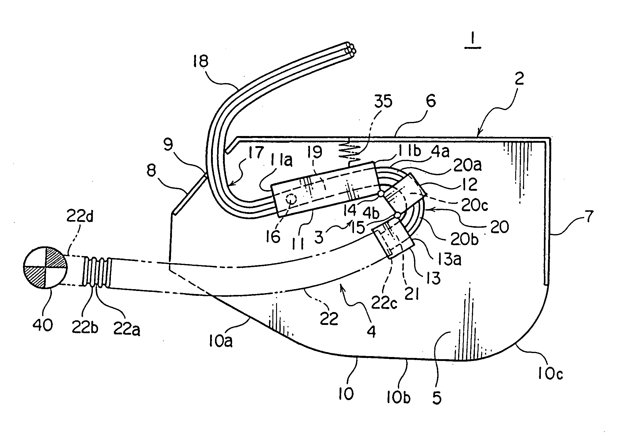
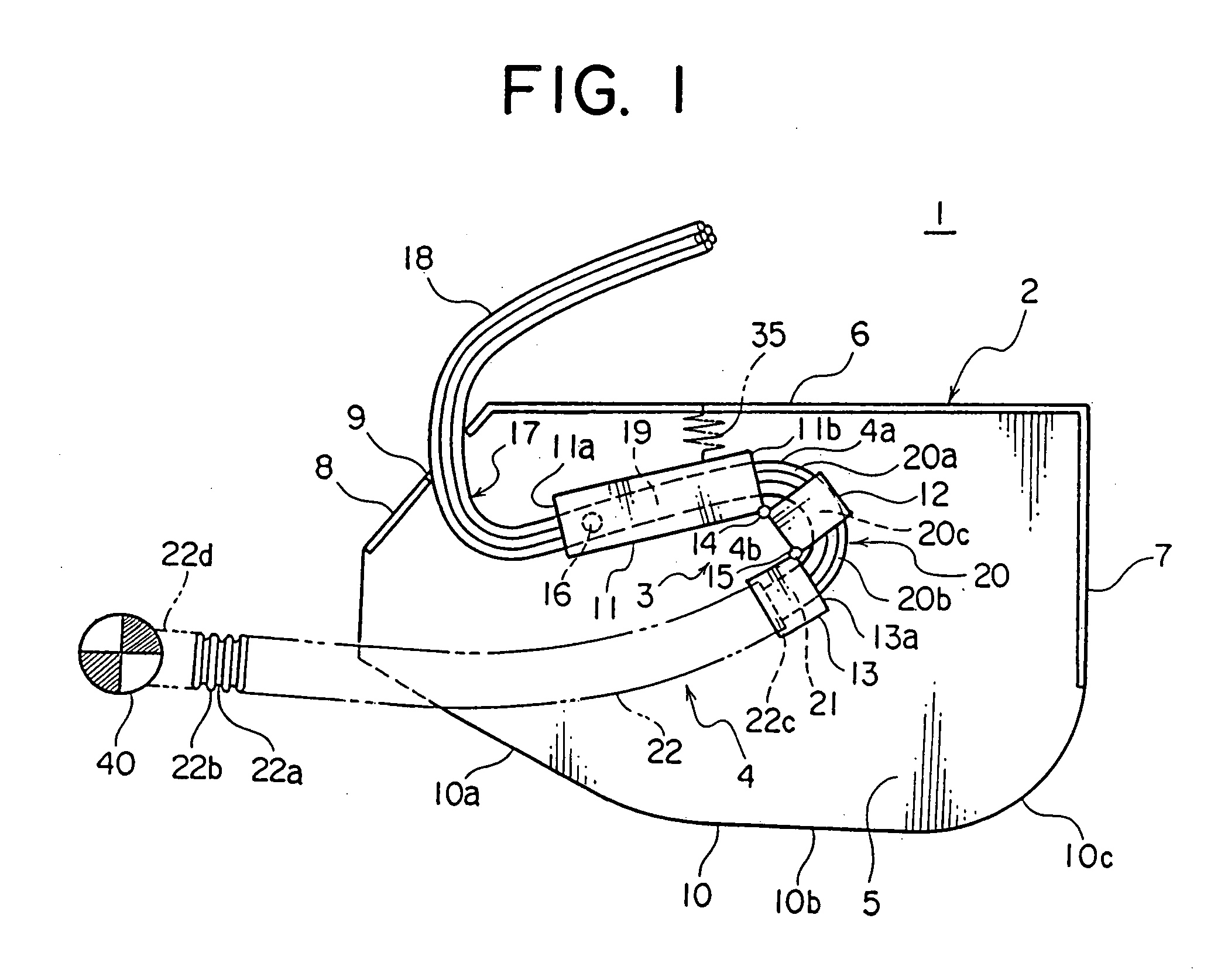
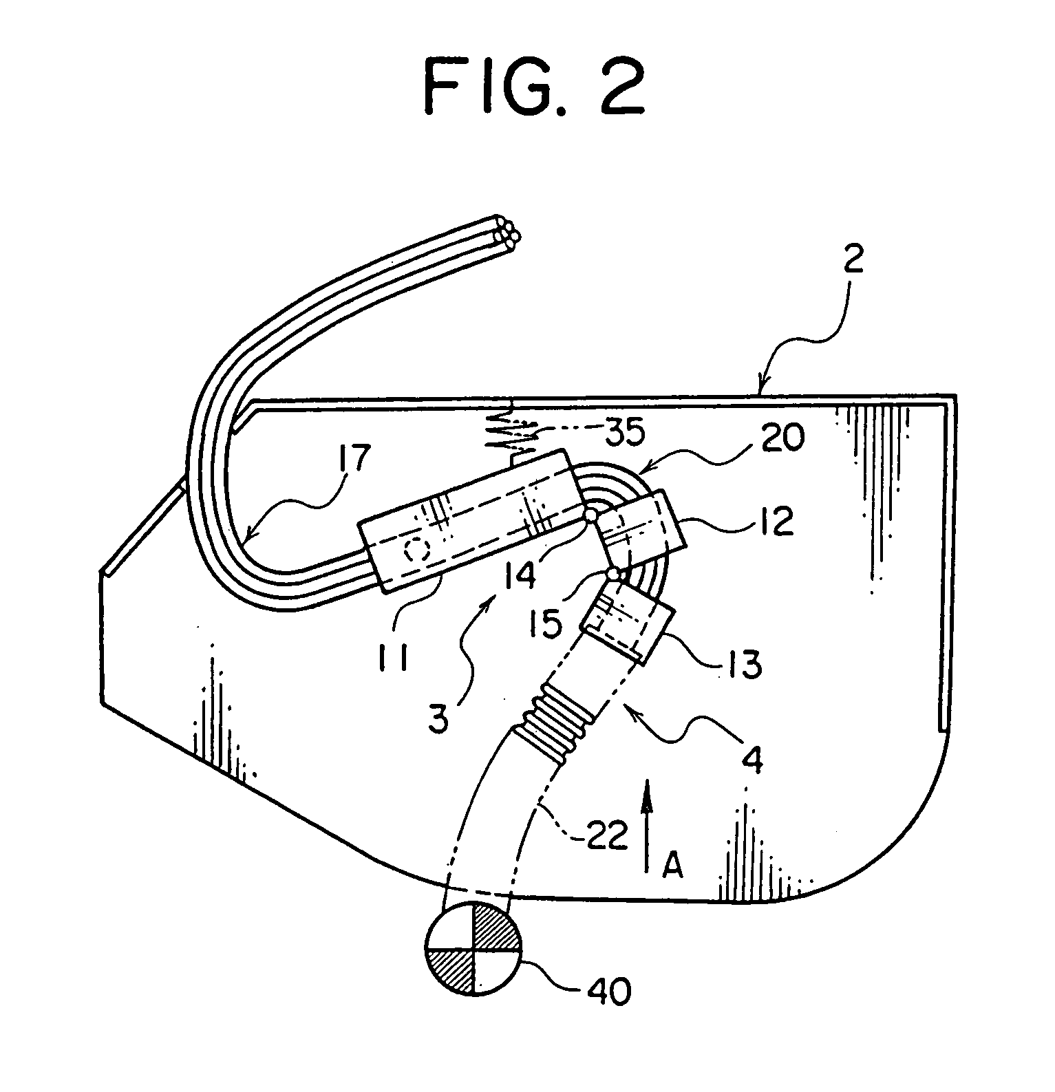
[0032]FIGS. 1-3 are an embodiment of an apparatus for holding a wire harness.

[0033]The apparatus 1 is vertically mounted on a sliding door (sliding configuration) of the left side of a motor vehicle. FIGS. 1-3 show the sliding door of the motor vehicle fully closed, partly opened, and fully opened, respectively.

[0034]Referring to FIG. 1, the apparatus 1 includes a case (protector) 2 made of a synthetic resin, a holder assembly 3 made of a synthetic resin and disposed on the case 2, one end of the holder assembly 3 being pivotally supported with an axle 16 (support portion), and a wire harness 4 flexibly arranged along the holder assembly 3 in the case 2. The holder assembly 3 is explained below by referring to FIGS. 4A and 4B.

[0035]The case 2 is smaller than the conventional case 42 and includes a base 2 (the same numeral as the case is used) and a cover (not shown). The case 2 has opposed base plates 5 and a circumferential wall including an upper wall 6, a front wall 7, and an inc...


PUM


Abstract

The present invention is to provide an apparatus for holding a wire harness. The apparatus includes a case and a holder assembly disposed inside the case. The holder assembly includes a first, a second, and a third holder. One end of the first holder is pivotally attached to a main body and another end thereof is connected with the second holder with a first hinge. The second holder is pivotally connected with the third holder with a second hinge. The wire harness is flexibly passed through the holder assembly. The wire harness is flexural between the first and the second holder, and between the second and the third holder. The apparatus reduces a required length of the wire harness and improves bending endurance thereof.

Description

BACKGROUND OF THE INVENTION[0001]1. Field of the Invention[0002]The present invention relates to an apparatus for flexibly holding a wire harness, which is disposed in a sliding door of a motor vehicle, with a holder assembly so that an excess portion of the wire harness can be received in the sliding door.[0003]2. Description of the Related Art[0004]FIGS. 5 and 6 show a conventional apparatus for holding a wire harness (JP, 2001-354085, A, FIGS. 4 and 7).[0005]The apparatus 50 is disposed on a sliding door 41 of a motor vehicle and includes a case 42 (protector), which is made of a synthetic resin and flexibly receives a wire harness 43, and a metal leaf spring 44 upwardly urging the wire harness 43 in the case 42.[0006]The case 42 includes a base 42 (the same reference numeral as the case) and a cover (not shown). The base 42 and the cover each have a base plate 51 and a circumferential wall 52. The cover is locked to the base 42 with a locking means. The base 42 is fixed to a pan...

Claims


Application Information

Patent Timeline
Patent Type & Authority Applications(United States)
IPC IPC(8): F16L3/08
CPCH02G11/006B60R16/027B60R16/0215
Inventor KOGURE, NAOTOTAKEMOTO, HISASHI
Owner YAZAKI CORP
Learn More