
High sensitivity, passive magnetic field sensor and method of manufacture

a passive magnetic field and high sensitivity technology, applied in the field of magnetic field sensors, can solve the problems of limiting the applications in which devices can be used, further limiting the application, and the field applied in this direction is less effective in rotating the magnetization than the field applied

Inactive Publication Date: 2008-09-04
FERRO SOLUTIONS
View PDF22 Cites 30 Cited by
  • Summary
  • Abstract
  • Description
  • Claims
  • Application Information

AI Technical Summary

Problems solved by technology

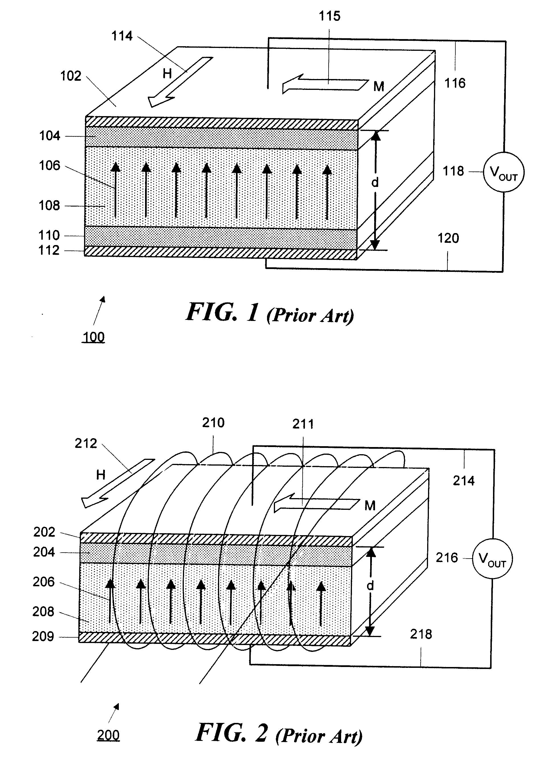
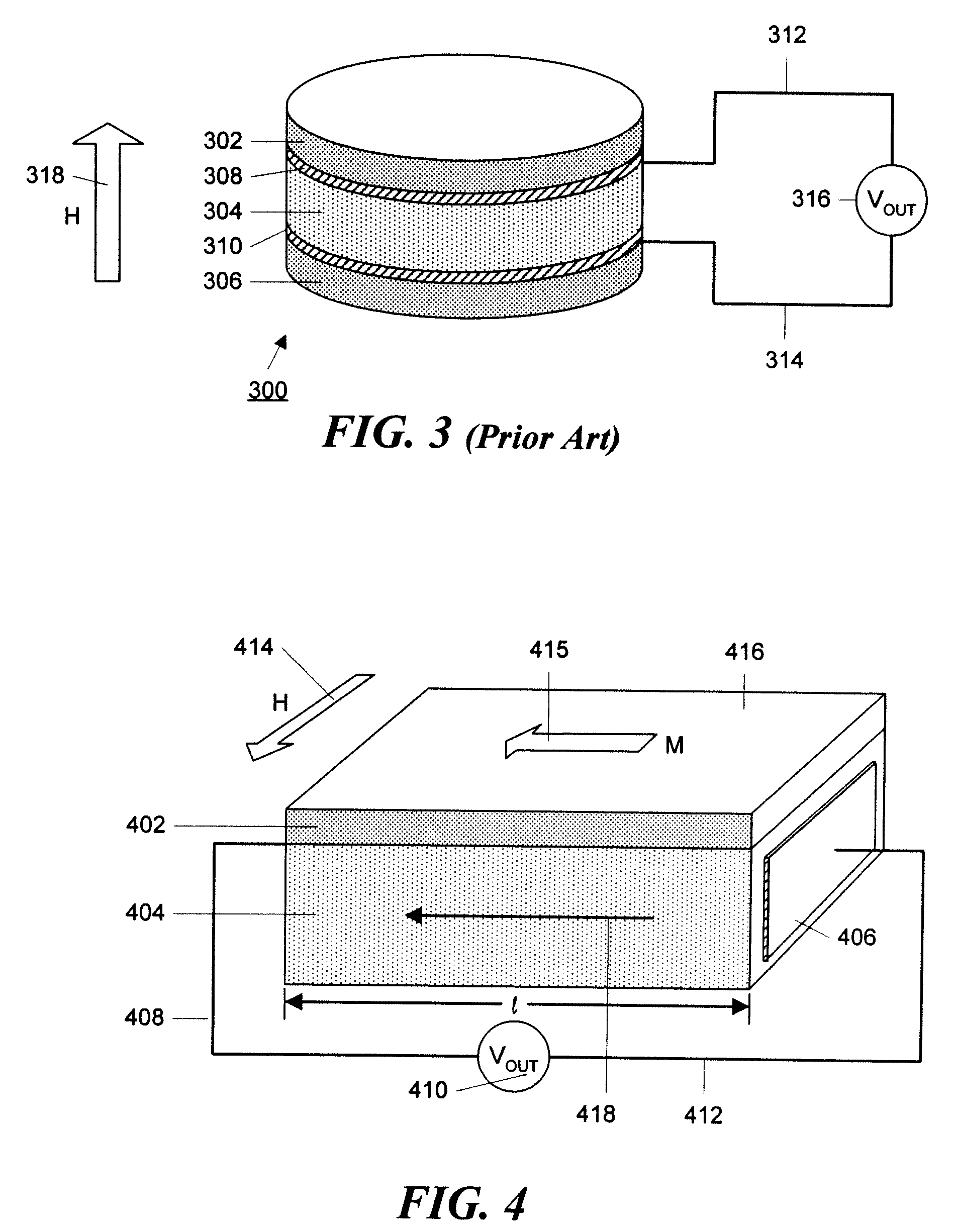
However, magnetization rotation in the plane of the magnetic layer does not generate a large voltage in the piezoelectric element in the direction normal to the magnetic layers.
These magnetic field sensitivities limit the applications in which the devices can be used.
In addition, the device shown in FIG. 2 requires power to generate the AC bias field and thus is further limited in its application.
A field applied in this direction is less effective in rotating the magnetization than a field applied in the plane of the sample because perpendicular magnetization requires a field that also must overcome magnetostatic energy.

Method used


Image

  • High sensitivity, passive magnetic field sensor and method of manufacture
  • High sensitivity, passive magnetic field sensor and method of manufacture
  • High sensitivity, passive magnetic field sensor and method of manufacture

Examples


embodiment 1600

[0055]FIG. 16 illustrates an embodiment 1600 in which the electroactive layer 1604 is also disk-shaped with a circular, or elliptical, cross section. The electroactive layer has a diameter, d, and a thickness, t, with d>t. Disk-shaped magnetostrictive layers 1602 and 1603 are bonded to the top and bottom faces of the disk 1604. The electrodes 1606 and 1607 are attached to the side wall of the disk 1604.

[0056]FIG. 17 illustrates an embodiment 1600 in which the electroactive layer 1504 is cylindrically shaped with a circular, or elliptical, cross section. The electroactive layer has a diameter, d, and a thickness, t, with d1702 and 1703 are bonded to the top and bottom faces of the cylinder 1704. The electrodes 1706 and 1707 are attached to the side wall of the cylinder 1704.

embodiment 1800

[0057]FIGS. 18-20 illustrate embodiments in which the electroactive material is either a solid cylinder or a hollow cylinder with a layer of magnetostrictive material bonded thereto and electrodes applied accordingly. For example, the embodiment 1800 shown in FIG. 18 utilizes a solid cylinder 1860 of electroactive material with one or more layers 1802 of magnetostrictive material wrapped around and bonded to the outer surface of the cylinder 1860. In this embodiment, the electrodes, of which electrode 1806 is shown in FIG. 18, are attached to the ends of the cylinder.

embodiment 1900

[0058]FIG. 19 shows an embodiment 1900 similar to that of FIG. 18 with the exception that the cylinder 1960 of electroactive material is hollow and ring-shaped electrodes (of which electrode 1906 is shown in FIG. 19) are applied to the ends of the cylinder.


PUM


Abstract

A magnetic field sensor comprises one or more magnetic layers of magnetostrictive material that is mechanically bonded to one or more layers of electroactive material. When a magnetic field is applied to the device, it rotates the magnetization that is present in the in the magnetostrictive material thereby generating a magnetostrictive stress in the material. The magnetostrictive stress generated by this layer, in turn, stresses the piezoelectric layer to which the magnetostrictive layer is bonded. In order to increase sensitivity, the voltage across the piezoelectric material is measured in a direction that is parallel to the plane in which the magnetization in the magnetic material rotates.

Description

RELATED APPLICATIONS[0001]This application claims the benefit of U.S. Provisional Application No. 60 / 431,487, filed Dec. 9, 2002.FIELD OF THE INVENTION[0002]This invention relates to magnetic field sensors, and specifically to solid-state magnetic field sensors that generate a voltage in response to an applied magnetic field by means of a magnetostrictive layer bonded to an electroactive layer.BACKGROUND OF THE INVENTION[0003]There are a variety of conventional devices for measuring magnetic field strength. These known devices include inductive pickup coils, Hall Effect probes, flux gate magnetometers, and magnetostrictive sensors. The latter class of sensors includes passive solid-state devices that comprise one or more magnetic layers of magnetostrictive material that are mechanically bonded to one or more layers of piezoelectric material. When a magnetic field is applied to the device, it rotates the magnetization that is present in the in the magnetostrictive material thereby ge...

Claims


Application Information

Patent Timeline
Patent Type & Authority Applications(United States)
IPC IPC(8): G01R33/18
CPCA61N1/3785A61N1/3787A61N2/006H02N11/002H01L41/00H02K57/003G01R33/18H02K99/10H10N35/00
Inventor HUANG, JIANKANGO'HANDLEY, ROBERT C.
Owner FERRO SOLUTIONS
Learn More