
Determinting a Detection Signal in a Spread Spectrum Communications System

a technology of a communication system and a detection signal, applied in the direction of multiplex communication, electrical equipment, transmission, etc., to achieve the effect of improving the overall detection performance of the combined signal and further improving the detection performan

Inactive Publication Date: 2008-09-04
TELEFON AB LM ERICSSON (PUBL)
View PDF4 Cites 37 Cited by
  • Summary
  • Abstract
  • Description
  • Claims
  • Application Information

AI Technical Summary

Benefits of technology

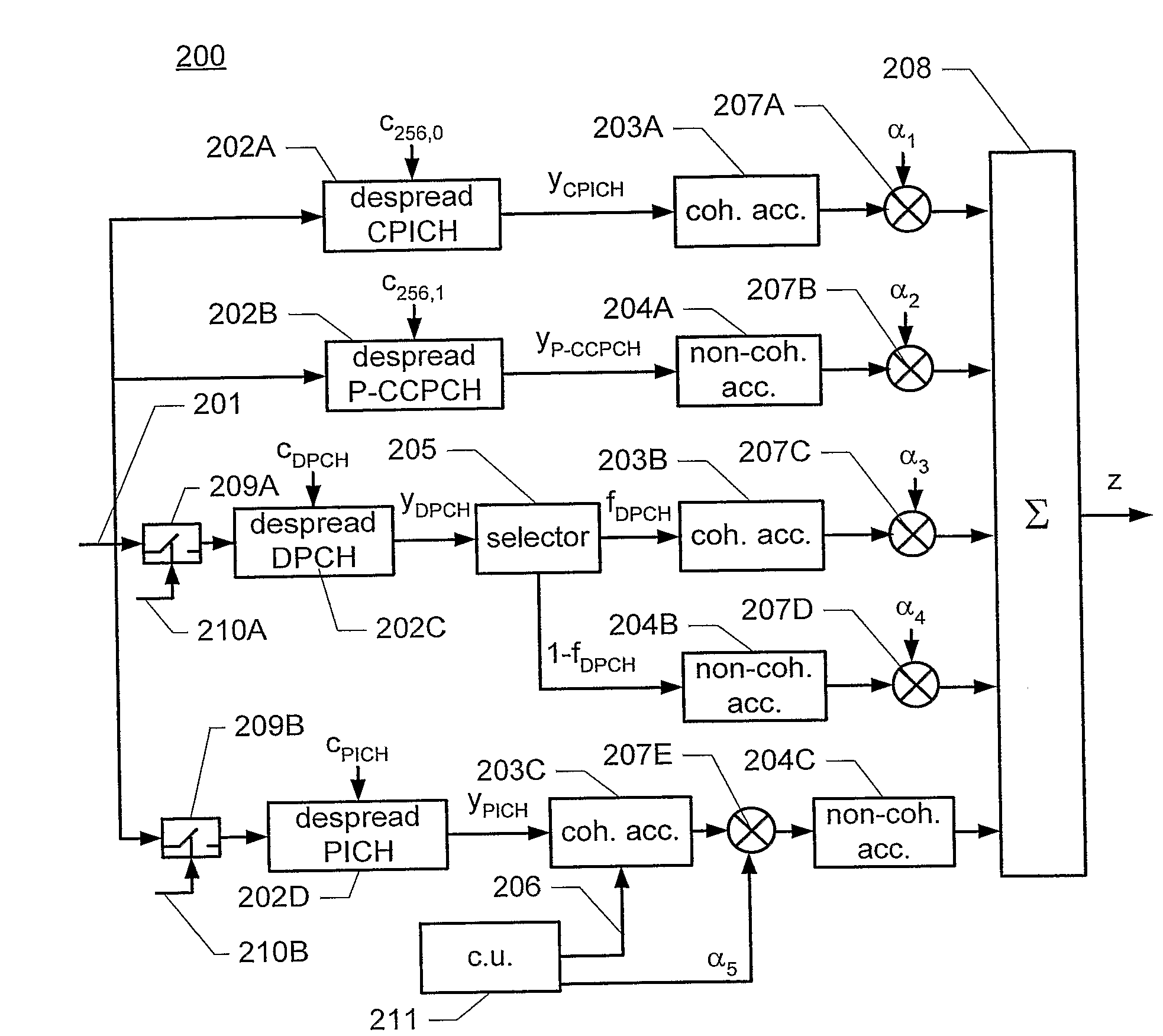
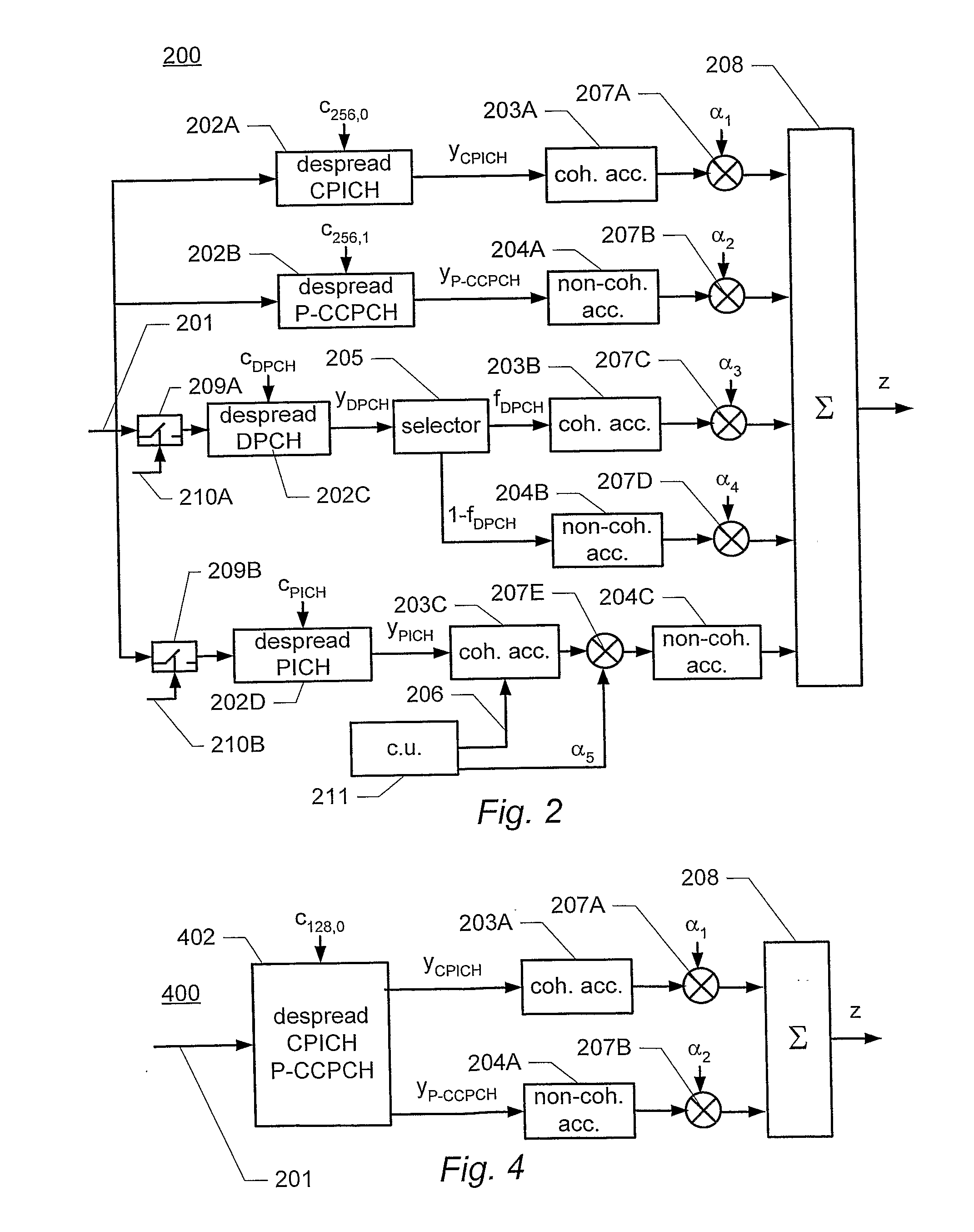
[0016]Hence, by selecting at least first and second subsets of known and unknown signal symbols, respectively, and by performing coherent correlation over the first subset of known symbols and non-coherent correlation over the second subset of unknown symbols, the correlation performance is further improved.
[0044]Consequently, coherent accumulation of the buffered signals is possible, even where the signal symbols are a priori unknown. In particular, since the received signal and / or the de-spread signal symbols are buffered while the receiver decodes the received signal and reconstructs the values of the transmitted signal symbols, the values of the signal symbols for the buffered signal are known.

Problems solved by technology

Even though this method improves the detection performance by using correlation of different channels, it remains a problem to further improve the detection performance.

Method used


Image

  • Determinting a Detection Signal in a Spread Spectrum Communications System
  • Determinting a Detection Signal in a Spread Spectrum Communications System
  • Determinting a Detection Signal in a Spread Spectrum Communications System

Examples


Embodiment Construction

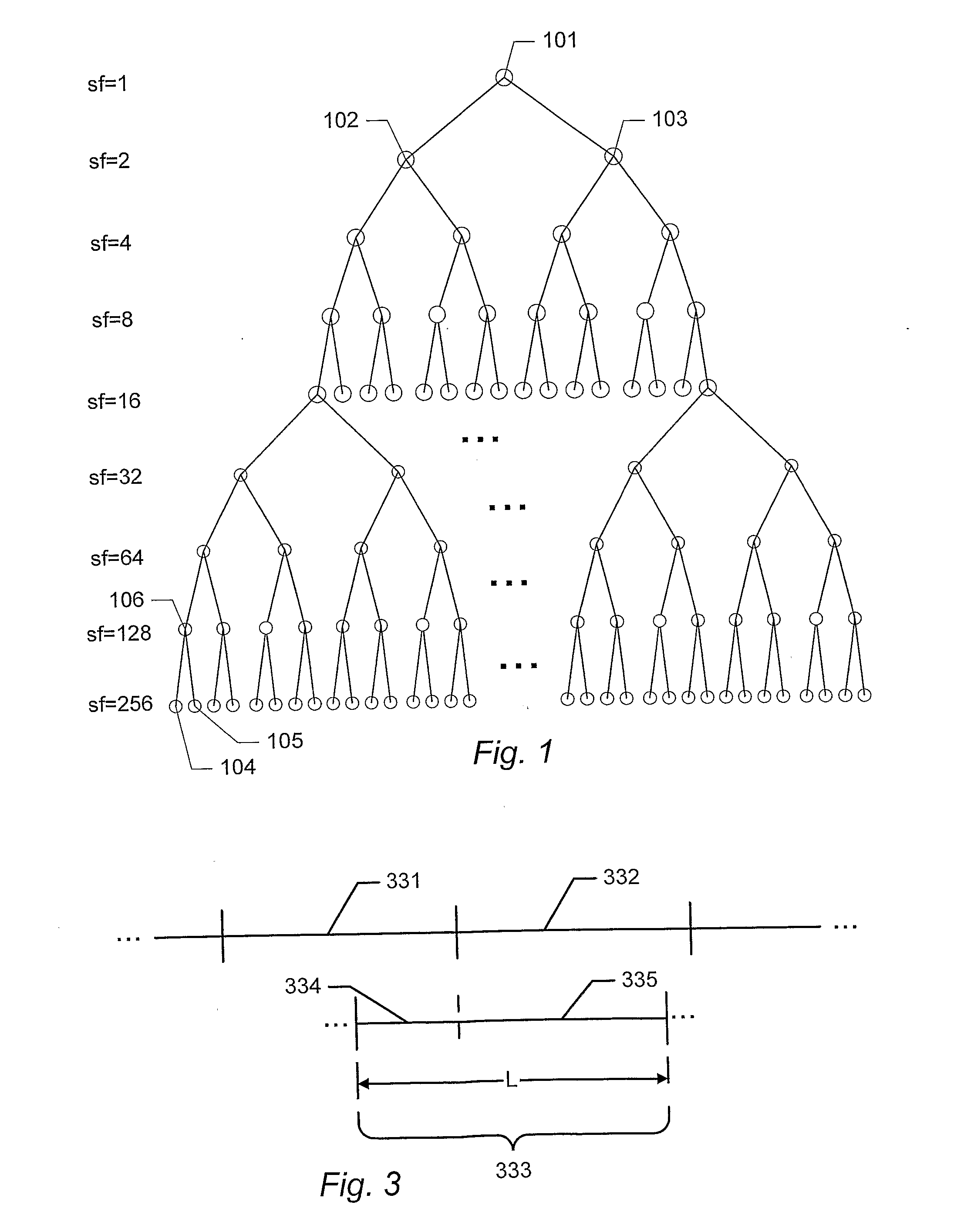
[0088]FIG. 1 illustrates the code tree of an embodiment of channelization codes used in a WCDMA system. An example of such a system is the 3GPP WCDMA system specified by the 3rd Generation Partnership Project (3GPP). A more detailed description of an example of the 3GPP WCDMA system can be found in the specification of the September 2004 release of 3GPP Release 5 published by the 3rd Generation Partnership Project (3GPP) and available on the Internet on www.3gpp.orq. In particular, the channel structure of this example of a WCDMA system is described in 3GPP TS 25.211 (http: / / www.3gpp.org / ftp / Specs / 2004-09 / Rel-5 / 25_series / 25211-560.zip). The multiplexing and channel coding of this example is described in 3GPP TS 25.212 (http: / / www.3gpp.orq / ftp / Specs / 2004-09 / Rel-5 / 25_series / 25212-590.zip). The spreading and modulation of this example is described in 3GPP TS 25.213 (http: / / www.3gpp.org / ftp / Specs / 2004-09 / Rel-5 / 25_series / 25213-550.zip). The physical layer procedures of this example are d...


PUM


Abstract

Disclosed is a method of generating a detection signal for detecting energy in a spread-spectrum signal, comprising: de-spreading the spread-spectrum signal by applying a predetermined spreading code to obtain a sequence of de-spread signal symbols (202A-202D); accumulating a number of said signal symbols to obtain a single detection signal. The accumulation includes: obtaining a first and a second subset of said de-spread signal symbols, wherein the symbols of the first subset have values that are known to the receiver or at least known to be the same for all symbols of the first subset, and wherein the symbols of the second subset have unknown values; coherently accumulating the symbols of the first subset to obtain a first partial detection signal (203A, 203B, 203C); non-coherently accumulating the symbols of the second subset to obtain a second partial detection signal (204A, 204B, 204C); and combining the first and second partial detection signals to obtain the single detection signal (208).

Description

TECHNICAL FIELD[0001]This invention relates to the generation of a detection signal for detecting energy in a received spread spectrum communications signal.BACKGROUND OF THE INVENTION[0002]Code Division Multiple Access (CDMA) systems are spread spectrum systems in which different physical channels are separated by different spreading codes, the so-called channelization codes. Hence, the received signal is modulated by the data to be transmitted and by the channelization code. The data modulation is performed at a predetermined bit rate, and the modulation with the channelization code is performed at a higher rate, the so-called chip rate, as the bits of the spreading signal are referred to as chips. The spreading factor corresponds to the ratio of the data bit duration to the chip duration. Hence, the spreading factor determines the number of chips contained in one symbol.[0003]In the wide-band code-division multiple access (WCDMA) system designed for 3GPP, the channelization codes...

Claims


Application Information

Patent Timeline
Patent Type & Authority Applications(United States)
IPC IPC(8): H04B1/707H04J13/00H04J13/18
CPCH04B1/7075H04B1/7077H04J13/18H04J13/0048H04B2201/70701H04B1/7085
Inventor NILSSON, JOHANBERNHARDSSON, BOLINDOFF, BENGT
Owner TELEFON AB LM ERICSSON (PUBL)
Learn More