Centrifugal casting die, method for manufacturing thereof as well as casting material, blade obtained therefrom and method for manufacturing thereof

a centrifugal casting and die body technology, applied in the direction of superimposed coating process, instruments, applications, etc., can solve the problems of silicone rubber being liable to be torn and left on the inner surface, requiring an extremely large amount of man-hours for removal from the inner surface of the die body, and unable to achieve uniform circumferentiality, etc., to achieve easy replacement and easy replacement

Inactive Publication Date: 2008-09-04
CANON CHEMICALS INC
View PDF17 Cites 2 Cited by
  • Summary
  • Abstract
  • Description
  • Claims
  • Application Information

AI Technical Summary

Benefits of technology

[0014]An object of the present invention is to provide a centrifugal casting die from which a centrifugally casting material is easily removable without using a die-lubricant, and which is capable of being repeatedly used and easily refreshed, as well as to provide a method for manufacturing such a casting die.

Problems solved by technology

When a center axis of the rotary shaft 110b is eccentric from a center axis of the inner surface 110c of the conventional die body 110 shown in FIG. 8, or the deviation from circular form of the inner surface 110c of the die body 110 is low, vibration occurs in the inner surface 110c of the die body 110 during the rotation of the casting die, causing the uneven distribution of centrifugal force in the circumferential direction thereof and results in an inconvenience in that a wall thickness of the obtained thin-walled resinous cylindrical material 111 lacks the uniformity in the circumferential direction.
Particularly, when the silicone rubber having the deterioration in releasability is removed from the inner surface of the die body, the silicone rubber is liable to be torn and left on the inner surface.
The complete removal thereof from the inner surface of the die body necessitates an extremely large amount of man-hours.
As a result, when the obtained thin-walled centrifugally casting material is processed to a blade or others of the electrophotographic apparatus, it is liable to adhere to a casting jig or others and difficult to be handled to lower the workability.

Method used


Image

  • Centrifugal casting die, method for manufacturing thereof as well as casting material, blade obtained therefrom and method for manufacturing thereof
  • Centrifugal casting die, method for manufacturing thereof as well as casting material, blade obtained therefrom and method for manufacturing thereof
  • Centrifugal casting die, method for manufacturing thereof as well as casting material, blade obtained therefrom and method for manufacturing thereof

Examples


Embodiment Construction

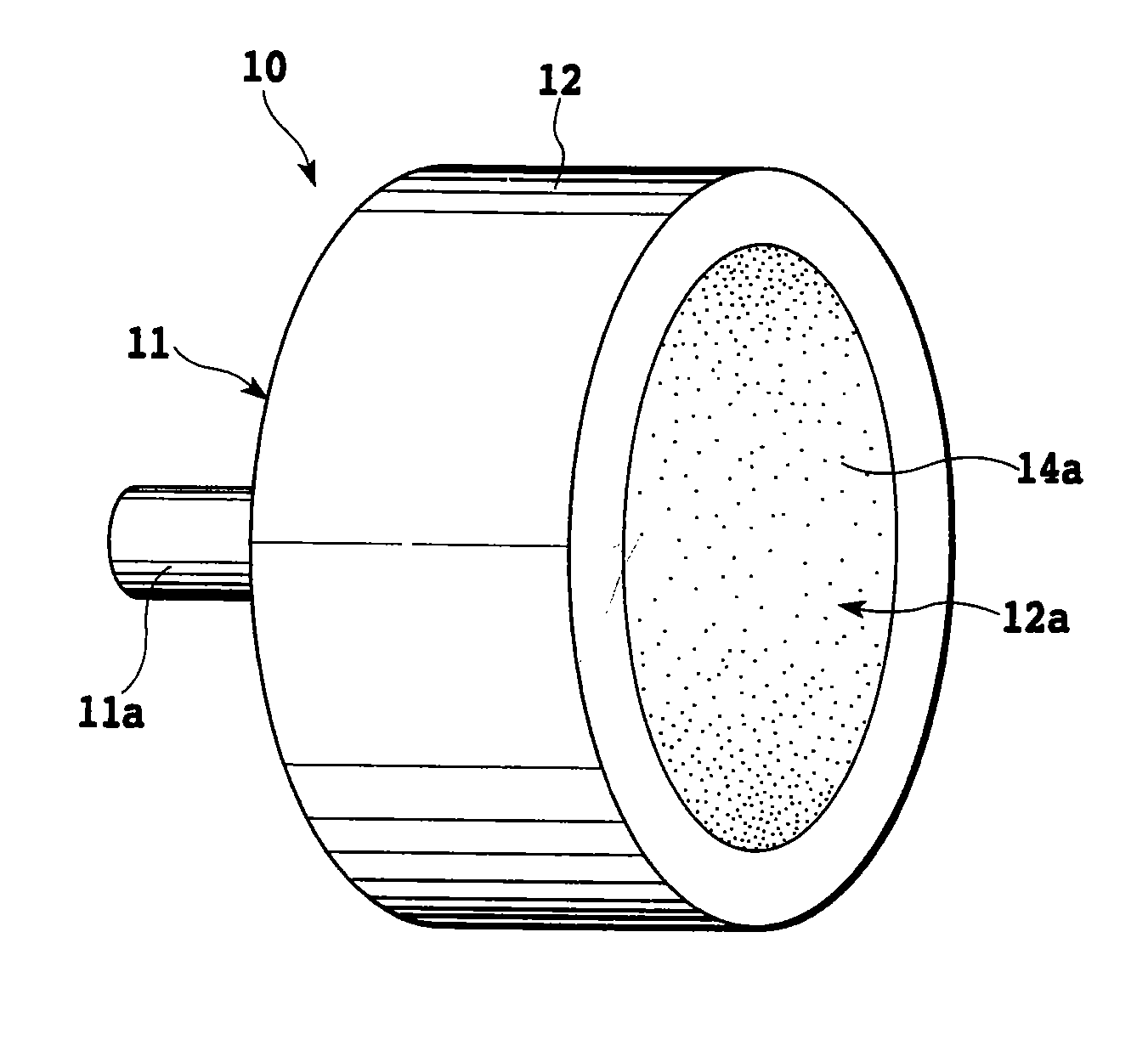
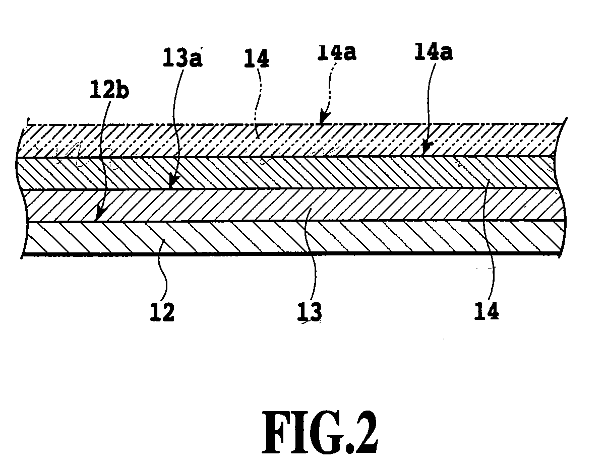
[0056]Embodiments of the present invention will be described in detail with reference to FIGS. 1 to 6, in which a centrifugal casting die according to the present invention is applied to the casting of a centrifugally casting material for producing a cleaning blade of an electrophotographic apparatus shown in FIG. 7. It is noted, however, the present invention should not be limited to these embodiments but includes all modifications and changes contained in a concept of the present invention defined by the scope of claim for patent in this specification. Accordingly, the present invention is, of course, applicable to other technologies belonging to the spirit thereof; for example, a developer blade of the above-mentioned electrophotographic apparatus.

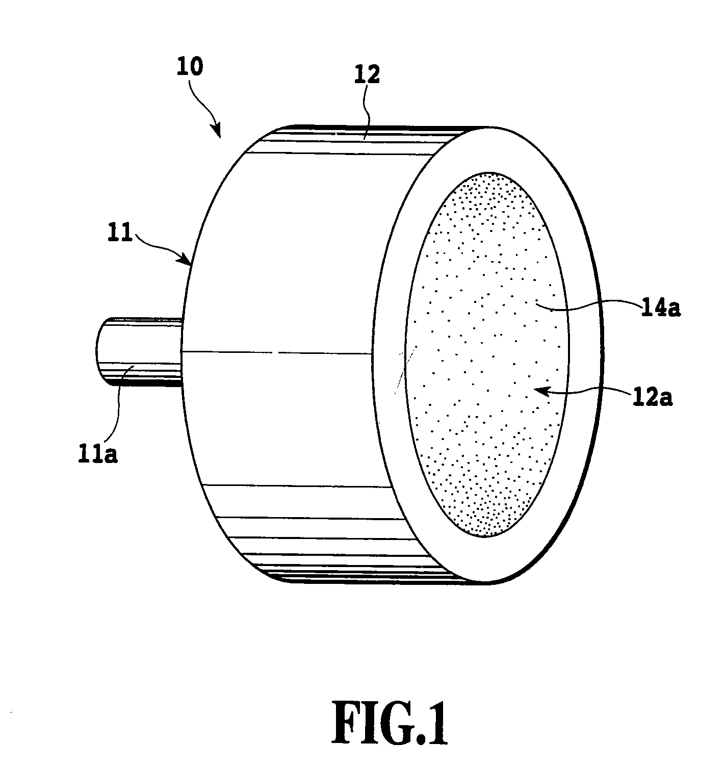
[0057]The appearance of a centrifugal casting die according to one embodiment of the present invention is schematically shown in FIG. 1, and a sectional view of a main portion thereof is shown in FIG. 2 in an enlarged manner. That is, a...


PUM

PropertyMeasurementUnit
particle sizeaaaaaaaaaa
surface roughness Rzaaaaaaaaaa
thicknessaaaaaaaaaa

Abstract

A centrifugal casting die according to the present invention includes a cylindrical die body, a backup layer releasably bonded to the inner surface 12b of the die body, and a top layer bonded to be integral to the inner surface of the backup layer, for holding a centrifugally casting material supplied to the inner surface thereof, whereby the centrifugally casting material having a uniform thickness is easily releasable from the centrifugal casting die without using a die-lubricant.

Description

[0001]This application claims priority from Japanese Patent Application Nos. 2002-136191 filed May 10, 2002, 2002-136190 filed May 10, 2002 and 2003-117441 filed Apr. 22, 2003, which are incorporated hereinto by reference.BACKGROUND OF THE INVENTION[0002]1. Field of the Invention[0003]The present invention relates to a centrifugal casting die for casting a thin-walled cylindrical resinous material and a method for manufacturing the casting die as well as the casting material by using the same, a blade used in an electrophotographic apparatus and a method for manufacturing the blade.[0004]2. Description of the Related Art[0005]A schematic structure of a conventional electrophotographic apparatus is shown in FIG. 7, which carries out a contact-charging process and a contact-transfer process without using a corona discharge. That is, an electro-photosensitive drum 101 on which an electrostatic latent image is formed is provided with an electroconductive basic layer made, for example, o...

Claims


Application Information

Patent Timeline
Patent Type & Authority Applications(United States)
IPC IPC(8): B28B21/42G03G15/00B29C33/40G03G15/08B29C39/08B29C39/26B29C41/04B29C41/40B29L23/00C23C28/00G03G21/10
CPCB29C33/405B29C39/26B29C39/08
Inventor TOMIYAMA, TAKASHIKUMANO, HISAOSATO, KOICHIHATANAKA, TAKU
Owner CANON CHEMICALS INC
Why Eureka
Try Eureka