Method for estimating thermal displacement in machine tool

Inactive Publication Date: 2008-09-04
OKUMA CORP
View PDF10 Cites 16 Cited by
  • Summary
  • Abstract
  • Description
  • Claims
  • Application Information

AI Technical Summary

Benefits of technology

[0050]In this method, the thermal displacement is estimated from the measured temperature, so that the measurement dead time can be compensated by calculating, based on the result of the response of the first-order lag element, the response delay caused by the attachment position and the temperature sensor with use of Expression 2 with respect to the compensation value for the equivalent heat value calculated with Expression 4, and adding the obtained result to the temperature for input calculation as a compensation temperature. FIG. 11 illustrates a residual error of the measured thermal displacement based on the method of the present invention, As is clear from the comparison between FIGS. 11 and 3,

Problems solved by technology

For this reason, when the dead time in temperature measurement is long, an error might be observed in the estimated value if ther

Method used


Image

  • Method for estimating thermal displacement in machine tool
  • Method for estimating thermal displacement in machine tool
  • Method for estimating thermal displacement in machine tool

Examples


Example

[0066]Embodiments of the present invention will hereinafter be described based on the drawings.

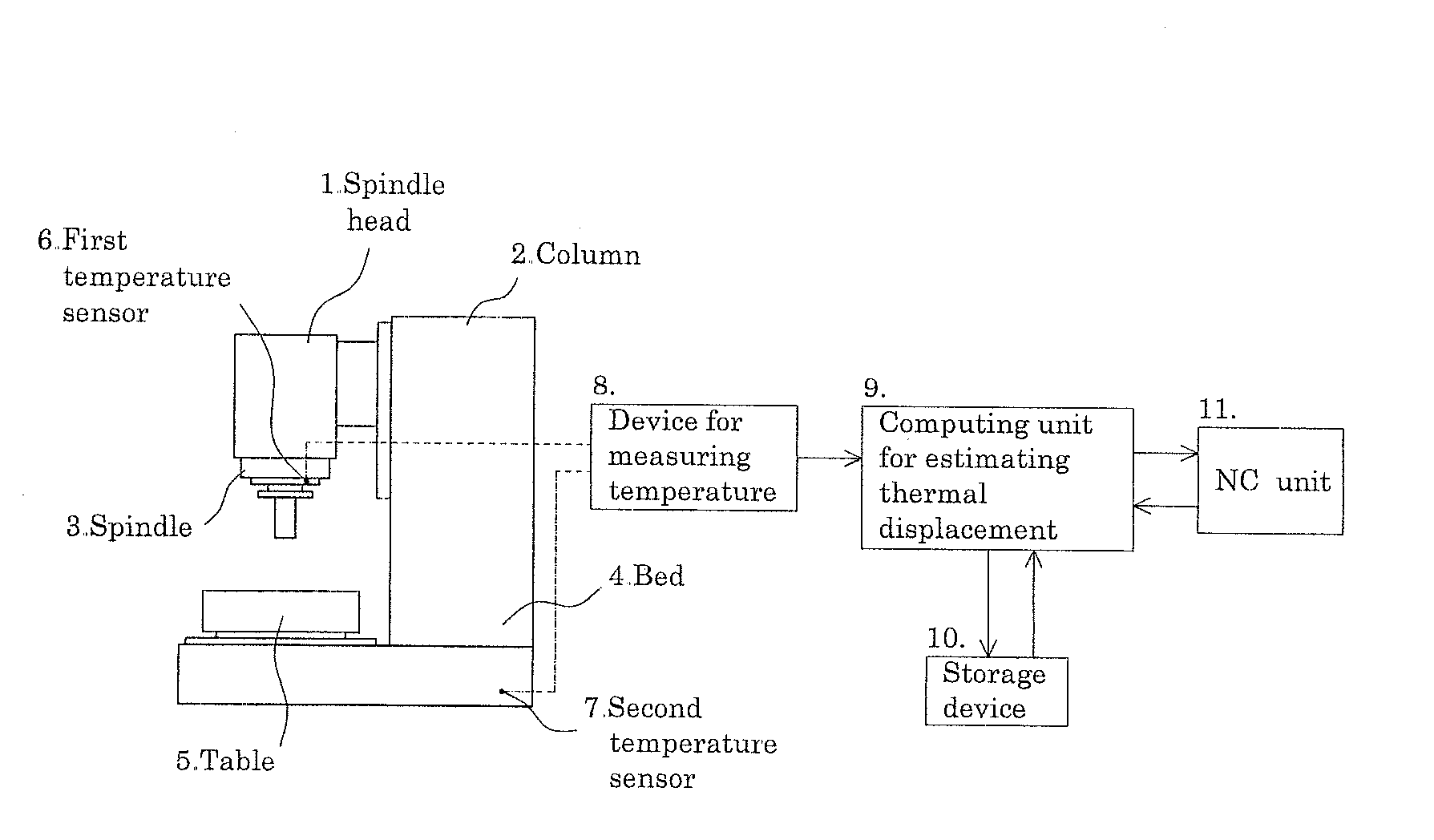
[0067]FIG. 12 illustrates a thermal displacement correcting system in a vertical machining center; a system similar to this may be applied to a horizontal machining center. The machining center substantially includes a spindle head 1, a column 2, a spindle 3, a bed 4, a moving table 5, etc., as is known. Near the spindle head 3, a first temperature sensor 6 for measuring a heat generation temperature of the spindle 3 is attached (see FIG. 6). Further, a second temperature sensor 7 for measuring a reference temperature is attached to the bed 4.

[0068]A device for measuring temperature 8 converts analog signals received from the respective temperature sensors 6 and 7 into digital signals, and outputs the digitalized temperature data to a computing unit for estimating thermal displacement 9. A storage device 10 preliminarily stores correcting parameters, parameters for the rotational speed of ...


PUM


Abstract

After a thermal displacement correcting program has started, a temperature is measured with a temperature sensor in S1, then when a rotational speed of a spindle is changed during the measurement (S2), a counter starts (S3). Then in S4, from a preset relationship between the rotational speed of the spindle and a setting-equivalent heat value, a correction factor that is a difference in setting-equivalent heat value between before and after the change in rotational speed of the spindle is calculated. Subsequently, in S5, a temperature-equivalent heat value is calculated, and then in S6, a compensation amount is calculated from the correction factor and a time elapsed after the change in rotational speed of the spindle. In S7, an equivalent heat value for compensating a dead time is obtained based on the sum of them S8, an estimated calculation for thermal displacement conversion is performed, and a correction process by an NC unit is performed in S9.

Description

[0001]This application claims the benefit of Japanese patent Application Number 2007-018314 filed on Jan. 29, 2007, the entirety of which is incorporated by reference.BACKFGROUND OF THE INVENTION[0002]1. Field of the Invention[0003]The present invention relates to a method for estimating a thermal displacement of a rotatable spindle in a machine tool such as a machining center.[0004]2. Description of the Background Art[0005]A machine tool generally has heat sources at different parts thereof (e.g., roller bearing for a spindle) in the nature of the machine, and heat generated by the heat sources is transmitted to various parts of the machine, which causes a thermal displacement of the machine body. As the thermal displacement of the machine body largely affects machining accuracy, a method for cooling heat generating parts, or a method for estimating a thermal displacement from machine body temperature information for correction has been conventionally widely employed.[0006]As the l...

Claims


Application Information

Patent Timeline
IPC IPC(8): G01K13/08G06F19/00B23Q15/18
CPCB23Q11/0007B23Q2220/006G05B2219/49206B23Q15/18
Inventor SENDA, HARUMITSU
Owner OKUMA CORP
Why Eureka
Try Eureka