Diagnostic device for internal combustion engine

a technology for internal combustion engines and diagnostic devices, which is applied in the direction of electrical control, exhaust treatment electric control, instruments, etc., can solve problems such as sensor failure types, and achieve the effect of reliably judging or diagnosing a condition of the detecting uni

Active Publication Date: 2008-09-04
DENSO CORP
View PDF21 Cites 25 Cited by
  • Summary
  • Abstract
  • Description
  • Claims
  • Application Information

AI Technical Summary

Benefits of technology

[0007]An object of the present invention is to provide, with due consideration to the drawbacks of the conventional diagnostic device, a diagnostic device that reliably judges or diagnoses a condition of a detecting unit which detects a differential pressure of an exhaust gas between upstream and downstream sides of an exhaust emission control device.
[0010]Accordingly, the diagnostic device can reliably judge or diagnose a condition of the detecting unit.

Problems solved by technology

However, there are many types of failure that can occur in the sensor.

Method used


Image

  • Diagnostic device for internal combustion engine
  • Diagnostic device for internal combustion engine
  • Diagnostic device for internal combustion engine

Examples


first modification

[0085]In the embodiment, each of the low and high flow rate regions is fixed by fixing the low and high flow rate threshold values VEXL and VEXH. However, as shown in FIG. 7, when a volume flow rate Vex of the exhaust gas is fixed, the differential pressure of the exhaust as is increased with the quantity of the accumulated particulate matters. Therefore, a difference between differential pressures of the exhaust gas at the values VEXL and VEXH is changed with the quantity of the accumulated particulate matters. To reliably judge or diagnose a condition of the sensor 40, a difference between differential pressures of the exhaust gas at the values VEXL and VEXH should be set to be equal to or larger than a predetermined pressure value corresponding to the fluctuation value Pf.

[0086]In this modification, as shown in FIG. 12, the ECU 50 further has a particulate matter quantity estimating block 56 and a threshold value setting block 57. When the sensor 40 is in a normal condition, the ...

second modification

[0088]In the embodiment, the low and high flow rate regions are determined by using the low and high flow rate threshold values VEXL and VEXH. However, the low and high flow rate regions may be determined by using an engine speed NE determined in the ECU 50 from data of the sensor 28. More specifically, the judging block 51 sets a first value and a second value higher than the first value. When the engine speed NE is equal to or lower than the first value, the judging block 51 judges the engine 10 to be operated in the low flow rate region. When the engine speed NE is equal to or higher than the second value, the judging block 51 judges the engine 10 to be operated in the high flow rate region.

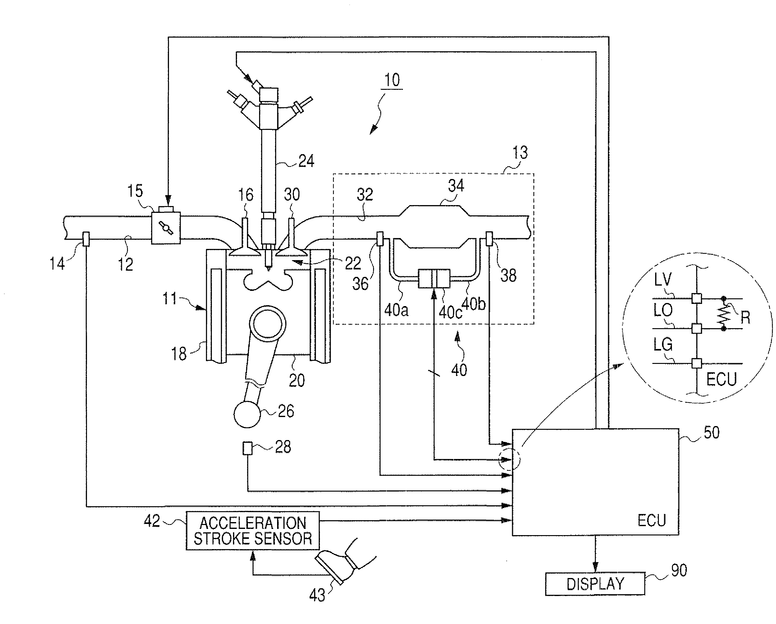
[0089]Further, the low and high flow rate regions may be determined by using a vehicle speed. A vehicle with the engine system shown in FIG. 1 has a vehicle speed sensor (not shown) for detecting a rotational speed of a transmission (not shown). The ECU 50 converts the rotational speed into a ...

third modification

[0093]In the embodiment, the block 64 or 53 of the ECU 50 judges or diagnoses directly from a difference between levels of the detection signal in the low and high flow rate regions whether the sensor 40 is in a normal condition or in a fault condition. However, as shown in FIG. 7, a quantity of the accumulated particulate matters can be estimated from a level of the detection signal and a volume flow rate Vex of the exhaust gas calculated in the calculating block 63. A quantity of the accumulated particulate matters is considerably changed with the volume flow rate Vex. With reference to FIG. 7, when the sensor 40 is in a normal condition, a first quantity of the accumulated particulate matters estimated from a first level of the detection signal and a first volume flow rate Vex of the exhaust gas in the low flow rate region is substantially equal to a second quantity of the accumulated particulate matters estimated from a second level of the detection signal and a second volume fl...


PUM


Abstract

A diagnostic device of an internal combustion engine diagnoses a condition of a differential pressure sensor. The sensor in a normal condition detects a differential pressure of an exhaust gas between upstream and downstream sides of a diesel particulate filter disposed in an exhaust system of the engine. The sensor in a fault condition detects no differential pressure of the exhaust gas. The device has a block obtaining a first signal from the sensor when the engine is operated in a low flow rate region of the exhaust gas and obtaining a second signal from the sensor when the engine is operated in a high flow rate region of the exhaust gas. A diagnostic block of the device judges from a difference between levels of the first and second signals whether the sensor is in the normal or fault condition.

Description

CROSS-REFERENCE TO RELATED APPLICATION[0001]This application is based upon and claims the benefit of priority of the prior Japanese Patent Application 2007-013356 filed on Jan. 24, 2007 so that the contents of which are incorporated herein by reference.BACKGROUND OF THE INVENTION[0002]1. Field of the Invention[0003]The present invention relates generally to a diagnostic device that diagnoses a failure or malfunction of a differential pressure detecting unit which detects a differential pressure of an exhaust gas at upstream and downstream sides of an exhaust emission control device disposed in an exhaust system of an internal combustion engine.[0004]2. Description of Related Art[0005]As an exhaust emission control device of an internal combustion engine, a diesel particulate filter (called DPF) is, for example, disposed in an exhaust system of a diesel engine to reduce hazardous materials included in an exhaust gas of the engine. In this system, a differential pressure detecting sen...

Claims


Application Information

Patent Timeline
Patent Type & Authority Applications(United States)
IPC IPC(8): F01N11/00F01N7/00F01N3/02F01N3/023F01N3/18F02D45/00
CPCF01N11/002Y02T10/47F01N2560/08Y02T10/40
Inventor KARIYA, YASUHIROKUBOSHIMA, TSUKASA
Owner DENSO CORP
Why Eureka
Try Eureka