Diagnostic device for internal combustion engine
a technology for internal combustion engines and diagnostic devices, which is applied in the direction of machines/engines, electrical control, instruments, etc., can solve problems such as sensor failure types, and achieve the effect of reliably judging or diagnosing a condition of the detecting uni
- Summary
- Abstract
- Description
- Claims
- Application Information
AI Technical Summary
Benefits of technology
Problems solved by technology
Method used
Image
Examples
first modification
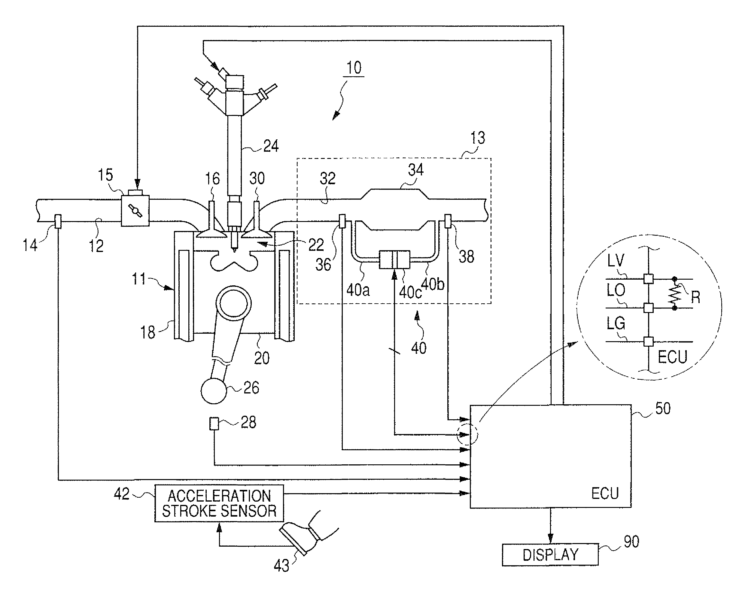
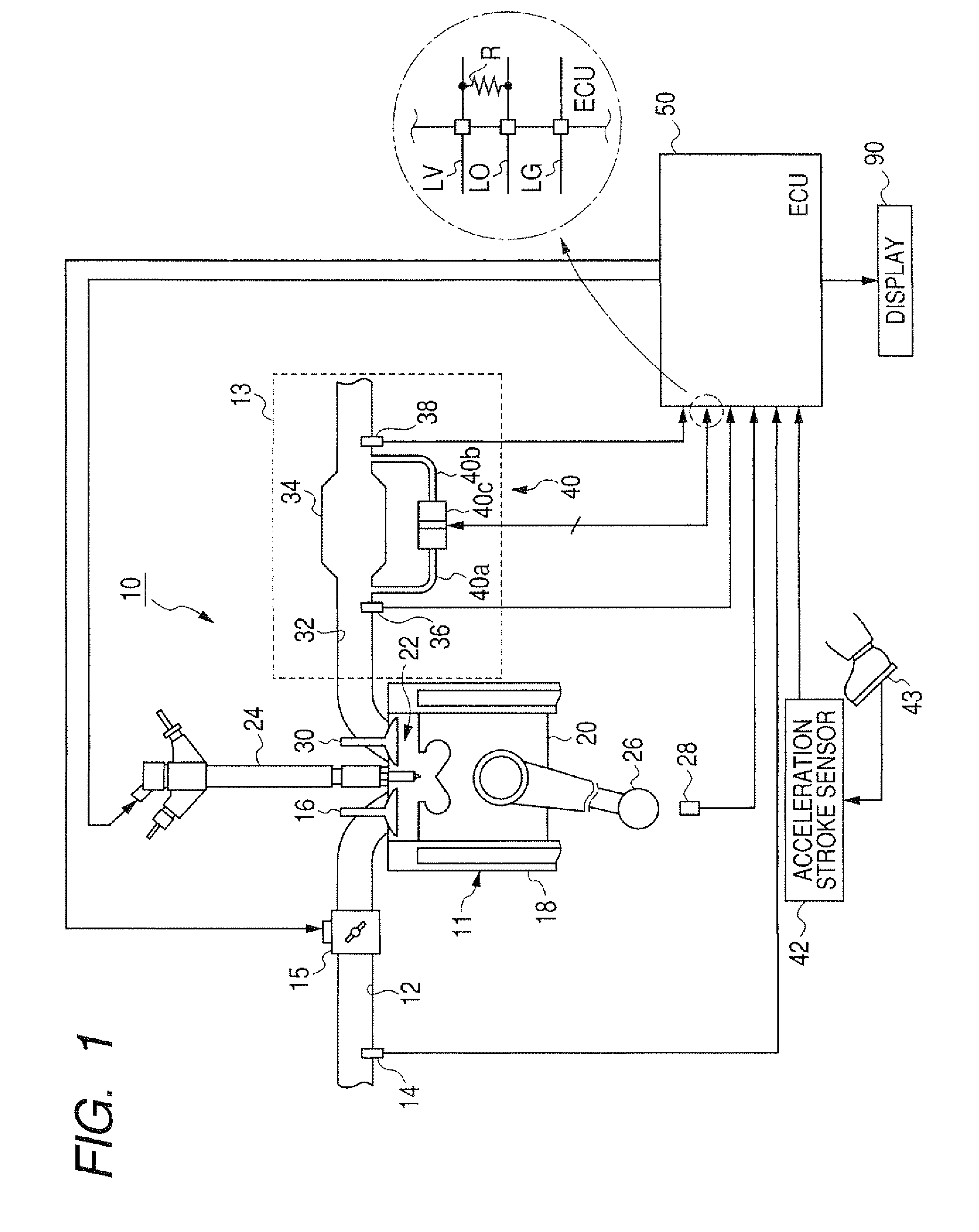
[0085]In the embodiment, each of the low and high flow rate regions is fixed by fixing the low and high flow rate threshold values VEXL and VEXH. However, as shown in FIG. 7, when a volume flow rate Vex of the exhaust gas is fixed, the differential pressure of the exhaust as is increased with the quantity of the accumulated particulate matters. Therefore, a difference between differential pressures of the exhaust gas at the values VEXL and VEXH is changed with the quantity of the accumulated particulate matters. To reliably judge or diagnose a condition of the sensor 40, a difference between differential pressures of the exhaust gas at the values VEXL and VEXH should be set to be equal to or larger than a predetermined pressure value corresponding to the fluctuation value Pf.
[0086]In this modification, as shown in FIG. 12, the ECU 50 further has a particulate matter quantity estimating block 56 and a threshold value setting block 57. When the sensor 40 is in a normal condition, the ...
second modification
[0088]In the embodiment, the low and high flow rate regions are determined by using the low and high flow rate threshold values VEXL and VEXH. However, the low and high flow rate regions may be determined by using an engine speed NE determined in the ECU 50 from data of the sensor 28. More specifically, the judging block 51 sets a first value and a second value higher than the first value. When the engine speed NE is equal to or lower than the first value, the judging block 51 judges the engine 10 to be operated in the low flow rate region. When the engine speed NE is equal to or higher than the second value, the judging block 51 judges the engine 10 to be operated in the high flow rate region.
[0089]Further, the low and high flow rate regions may be determined by using a vehicle speed. A vehicle with the engine system shown in FIG. 1 has a vehicle speed sensor (not shown) for detecting a rotational speed of a transmission (not shown). The ECU 50 converts the rotational speed into a ...
third modification
[0093]In the embodiment, the block 64 or 53 of the ECU 50 judges or diagnoses directly from a difference between levels of the detection signal in the low and high flow rate regions whether the sensor 40 is in a normal condition or in a fault condition. However, as shown in FIG. 7, a quantity of the accumulated particulate matters can be estimated from a level of the detection signal and a volume flow rate Vex of the exhaust gas calculated in the calculating block 63. A quantity of the accumulated particulate matters is considerably changed with the volume flow rate Vex. With reference to FIG. 7, when the sensor 40 is in a normal condition, a first quantity of the accumulated particulate matters estimated from a first level of the detection signal and a first volume flow rate Vex of the exhaust gas in the low flow rate region is substantially equal to a second quantity of the accumulated particulate matters estimated from a second level of the detection signal and a second volume fl...
PUM
 Abstract
Description
Claims
Application Information
 - R&D
- Intellectual Property
- Life Sciences
- Materials
- Tech Scout
- Unparalleled Data Quality
- Higher Quality Content
- 60% Fewer Hallucinations
Browse by: Latest US Patents, China's latest patents, Technical Efficacy Thesaurus, Application Domain, Technology Topic, Popular Technical Reports.
© 2025 PatSnap. All rights reserved.Legal|Privacy policy|Modern Slavery Act Transparency Statement|Sitemap|About US| Contact US: help@patsnap.com


