Communication monitoring system, communication monitoring apparatus and communication control apparatus

a communication monitoring and control apparatus technology, applied in the field of communication monitoring systems, communication monitoring apparatuses and communication control apparatuses, can solve the problems of increasing difficulty in detection and combatting bots, no longer sufficient measures are created, and the trend of more and more difficult to detect and combat bots

Inactive Publication Date: 2008-09-04
SECUREWARE INC
View PDF3 Cites 1 Cited by
  • Summary
  • Abstract
  • Description
  • Claims
  • Application Information

AI Technical Summary

Benefits of technology

[0018]According to the present application, the detecting section for detecting the shellcode and the storing section for storing the communications after the detection of the bot

Problems solved by technology

It is very difficult to detect and combat such a bot by the conventional antivirus softwares using pattern files (description files).
Therefore, no longer sufficient measures are created under present circumstances.
Consequently, there is a trend to more and more difficult to detect and com

Method used


Image

  • Communication monitoring system, communication monitoring apparatus and communication control apparatus
  • Communication monitoring system, communication monitoring apparatus and communication control apparatus
  • Communication monitoring system, communication monitoring apparatus and communication control apparatus

Examples


embodiment 1

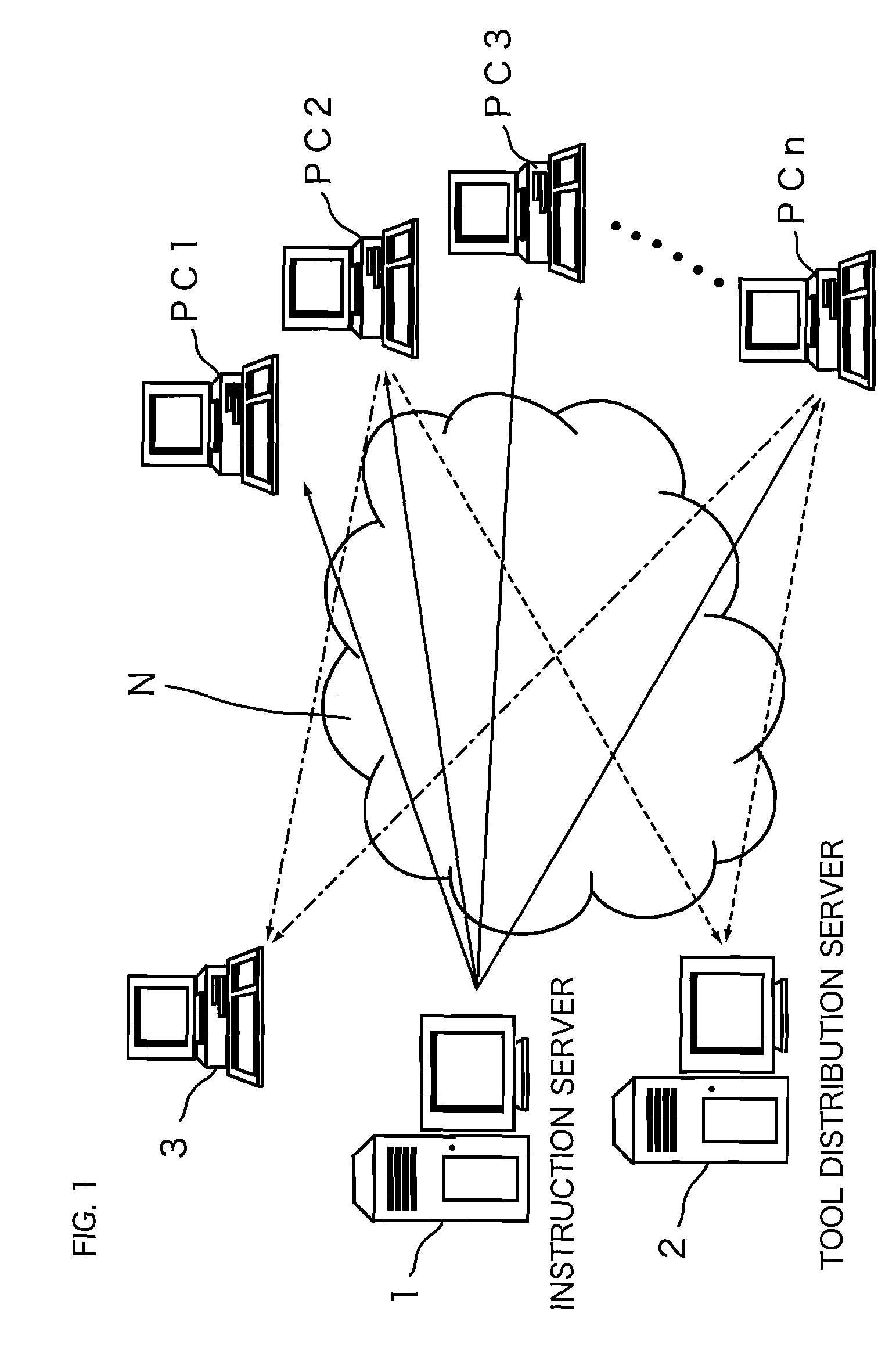
[0031]FIG. 1 is an explanatory view explaining a schematic structure of a botnet. There are a lot of hosts on an internet N. One of the hosts (or a plurality of the hosts) becomes an instruction server 1 for transmitting a shellcode. The instruction server 1 transmits the shellcode to information processing apparatuses PC1, PC2, PC3, . . . , PCn as being other hosts. The hosts (for example, the information processing apparatuses PC2 and PCn in FIG. 1) which execute the shellcode obtain a tool or the executable codes involved in the bot from a tool distribution server 2.

[0032]The information processing apparatuses PC2 and PCn which obtain the tool and the the executable codes involved in the bot (i.e. infected with the bot) attempt a DoS attack or transmission of spam.

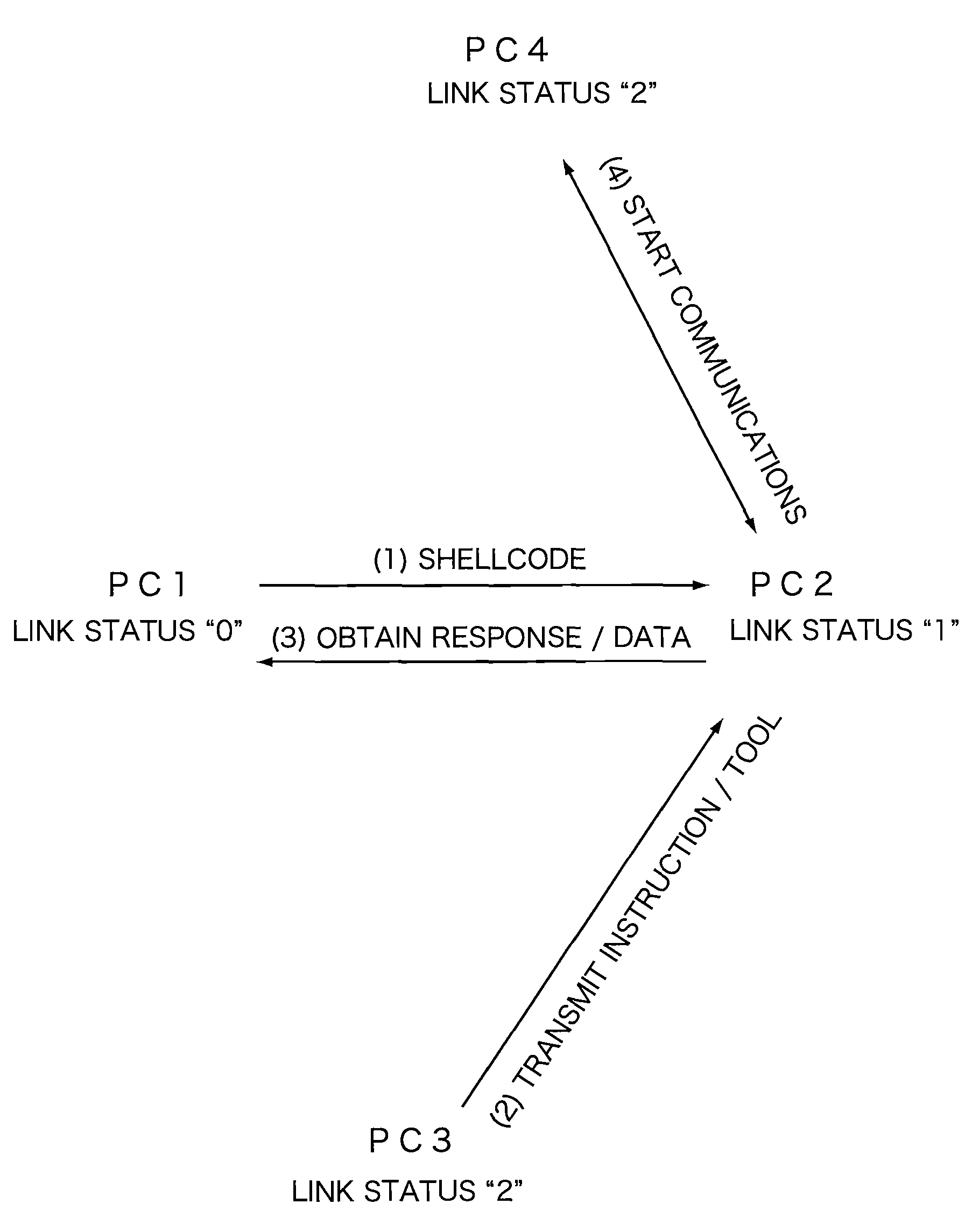
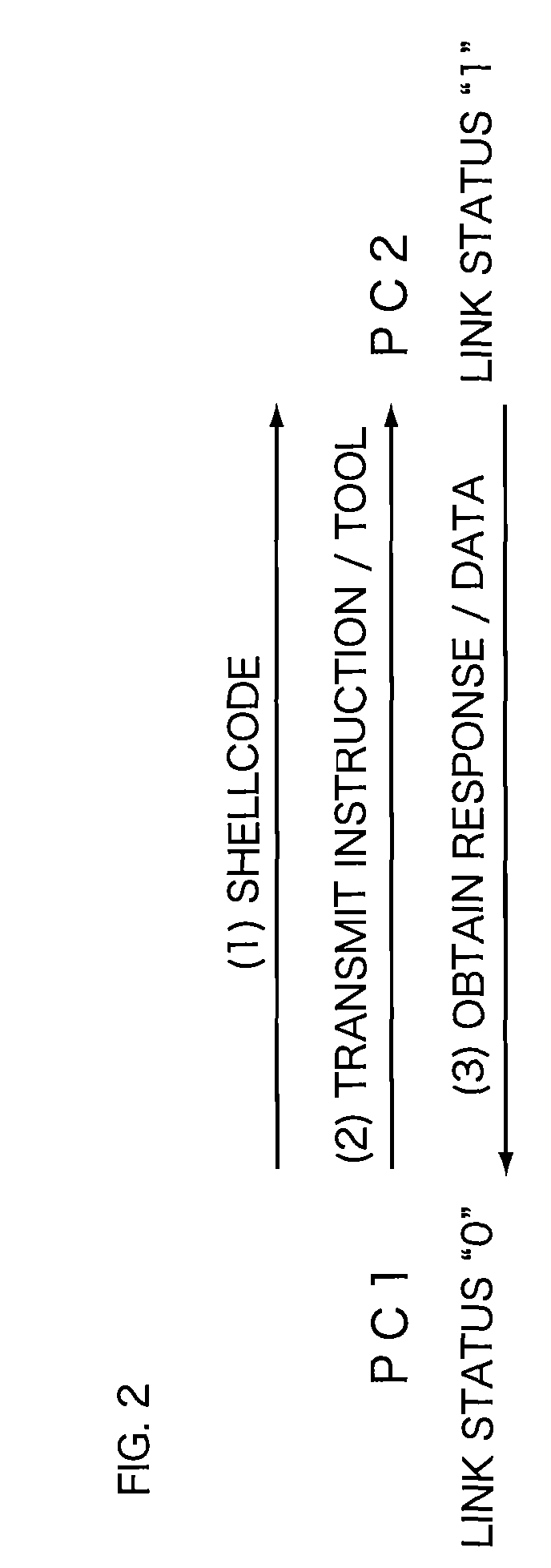
[0033]FIG. 2 to FIG. 4 are explanatory views explaining examples of the attack by the botnet. FIG. 2 shows an example of the attack between two nodes (for example, the information processing apparatuses PC1 and PC2) on ...

embodiment 2

[0053]Although the communication monitoring apparatuses S1 to Sn monitors the communications on the internet N in the first embodiment, the monitoring result in each of the communication monitoring apparatuses S1 to Sn may be summarized for controlling the communications.

[0054]FIG. 8 is an explanatory view explaining a schematic structure of a communication monitoring system according to the second embodiment. The communication monitoring apparatuses A1 to An are provided between a internet and LANs. Each of the communication monitoring apparatuses A1, A2, . . . , An transmits the monitoring result to the communication control apparatus 10.

[0055]Each of the communication monitoring apparatuses A1, A2, . . . , An has a IDS mode (IDS: Intrusion Detection System) and a IDP mode (IDP: Intrusion Detection and Prevention). In normal times, the communication monitoring apparatuses A1, A2, . . . , An collect the attack information at the IDS mode, and transmit the results to the communicati...


PUM


Abstract

A communication monitoring apparatus for monitoring communication data which are transmitted among a plurality of nodes on a network, includes a detecting section for detecting whether or not a shellcode is included in communication data transmitted and received between at least two nodes within the plurality of nodes and a storing section for storing communication data transmitted from the two nodes as being starting points during a predetermined time, when the detecting section detected the shellcode in communication data.

Description

CROSS-REFERENCE TO RELATED APPLICATIONS[0001]This Nonprovisional application claims priority under 35 U.S.C. §119(a) on Patent Application No. 2006-356062 filed in Japan on Dec. 28, 2006, the entire contents of which are hereby incorporated by reference.BACKGROUND[0002]1. Technical Field[0003]The present application relates to a communication monitoring system, a communication monitoring apparatus and a communication control apparatus for monitoring an operation of malicious softwares.[0004]2. Description of the Related Art[0005]Recently, a botnet is a serious threat for an internet (for example, see page 66 to 77 in Aug. 14, 2006 issue of NIKKEI PERSONAL COMPUTING). The botnet is a network constructed from an attacker, a control server and a lot of infected computers with the bot. A bot is a malicious program, and has a infection function to other computer and a updating function of the program. The infected computers with the bot performs the DoS attack to other computers, transmi...

Claims


Application Information

Patent Timeline
IPC IPC(8): G06F15/173G06F21/00G06F21/56
CPCH04L12/2602H04L2463/144H04L63/1416H04L29/06H04L43/12H04L43/00H04L9/40
Inventor SAITO, KAZUNORINOGAWA, HIROKIKOBAYASHI, TOSHIOMORIYA, SEIJI
Owner SECUREWARE INC
Why Eureka
Try Eureka