
Data bus bandwidth scheduling in an fbdimm memory system operating in variable latency mode

Inactive Publication Date: 2008-09-04
GLOBALFOUNDRIES INC
View PDF8 Cites 60 Cited by
  • Summary
  • Abstract
  • Description
  • Claims
  • Application Information

AI Technical Summary

Benefits of technology

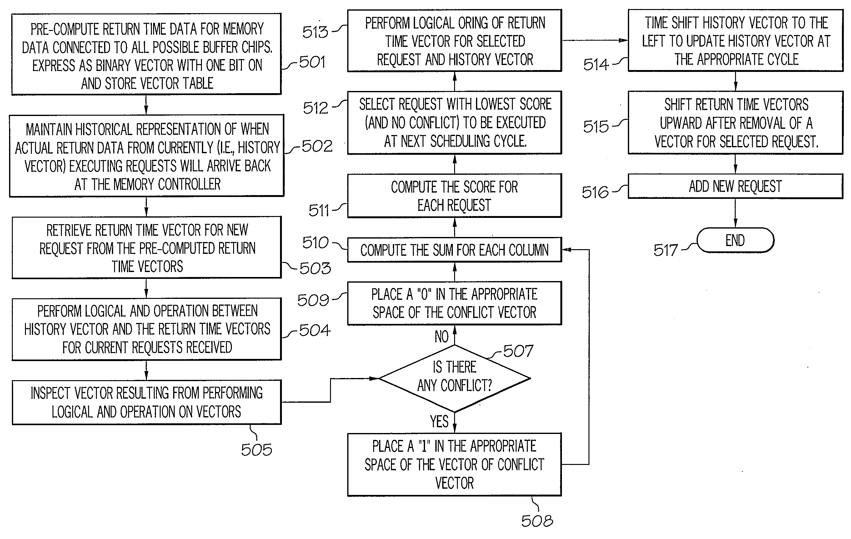
[0011]Disclosed is a method and system for efficiently scheduling servicing of data requests in a Fully Buffered Dual Inline Memory Module (FBDIMM) memory sub-system, using the variable latency mode. High speed integrated circuitry embodies a scheduling algorithm which pre-computes return time parameters for Dynamic Random Access Memory (DRAM) data connected (via a parallel Double Data Rate (DDR)-based interface) to a plurality of buffer chips. The return time parameters are a compilation of all possible values for the time interval between sending a command packet from the memory controller to retrieve data from the various memory locations and receiving the requested data at the memory controller. Each possible value of the time interval is expressed as a binary vector, with one bit “on” (i.e., set to “1”). The algorithm stores the set of return time vectors in a table, for use by the memory controller when a memory access request is received.

Problems solved by technology

Also, another component of the time delay seen by the memory controller is the time taken for the command packet to reach the destination buffer chip and for that buffer chip to send the requested data once the buffer chip has obtained the data from the DRAM chips.
However, the disadvantage is that all memory requests are delayed to match the delay of the slowest or farthest DRAM.
However, the drawback is that since all return data must pass through the same chain of buffer chips, a burden is placed on the memory controller to time the requests in a manner that avoids bus conflicts when returning data from different DRAMs.

Method used


Image

  • Data bus bandwidth scheduling in an fbdimm memory system operating in variable latency mode
  • Data bus bandwidth scheduling in an fbdimm memory system operating in variable latency mode
  • Data bus bandwidth scheduling in an fbdimm memory system operating in variable latency mode

Examples


Embodiment Construction

[0022]The present invention provides a method and system for efficiently scheduling servicing of data requests in a Fully Buffered Dual Inline Memory Module (FBDIMM) memory sub-system, using the variable latency mode. High speed integrated circuitry embodies a scheduling algorithm which pre-computes return time parameters for Dynamic Random Access Memory (DRAM) data connected (via a parallel Double Data Rate (DDR)-based interface) to a plurality of buffer chips. The return time parameters are a compilation of all possible values for the time interval between sending a command packet from the memory controller to retrieve data from the various memory locations and receiving the requested data at the memory controller. Each possible value of the time interval is expressed as a binary vector, with one bit “on” (i.e., set to “1”). The algorithm stores the set of return time vectors in a table, for use by the memory controller when a memory access request is received.

[0023]For each data ...


PUM


Abstract

A method and system for scheduling the servicing of data requests, using the variable latency mode, in an FBDIMM memory sub-system. A scheduling algorithm pre-computes return time data for data connected to all DRAM buffer chips and stores the return time data in a table. The return time data is expressed as a set of data return time binary vectors with one bit equal to “1” in each vector. For each received data request, the memory controller retrieves the appropriate return time vector. Additionally, the scheduling algorithm utilizes an updated history vector representing a compilation of data return time vectors of all executing requests to determine whether the received request presents a conflict to the executing requests. By computing and utilizing a score for each request, the scheduling algorithm re-orders and schedules the execution of selected requests to preserve as much data bus bandwidth as possible, while avoiding conflict.

Description

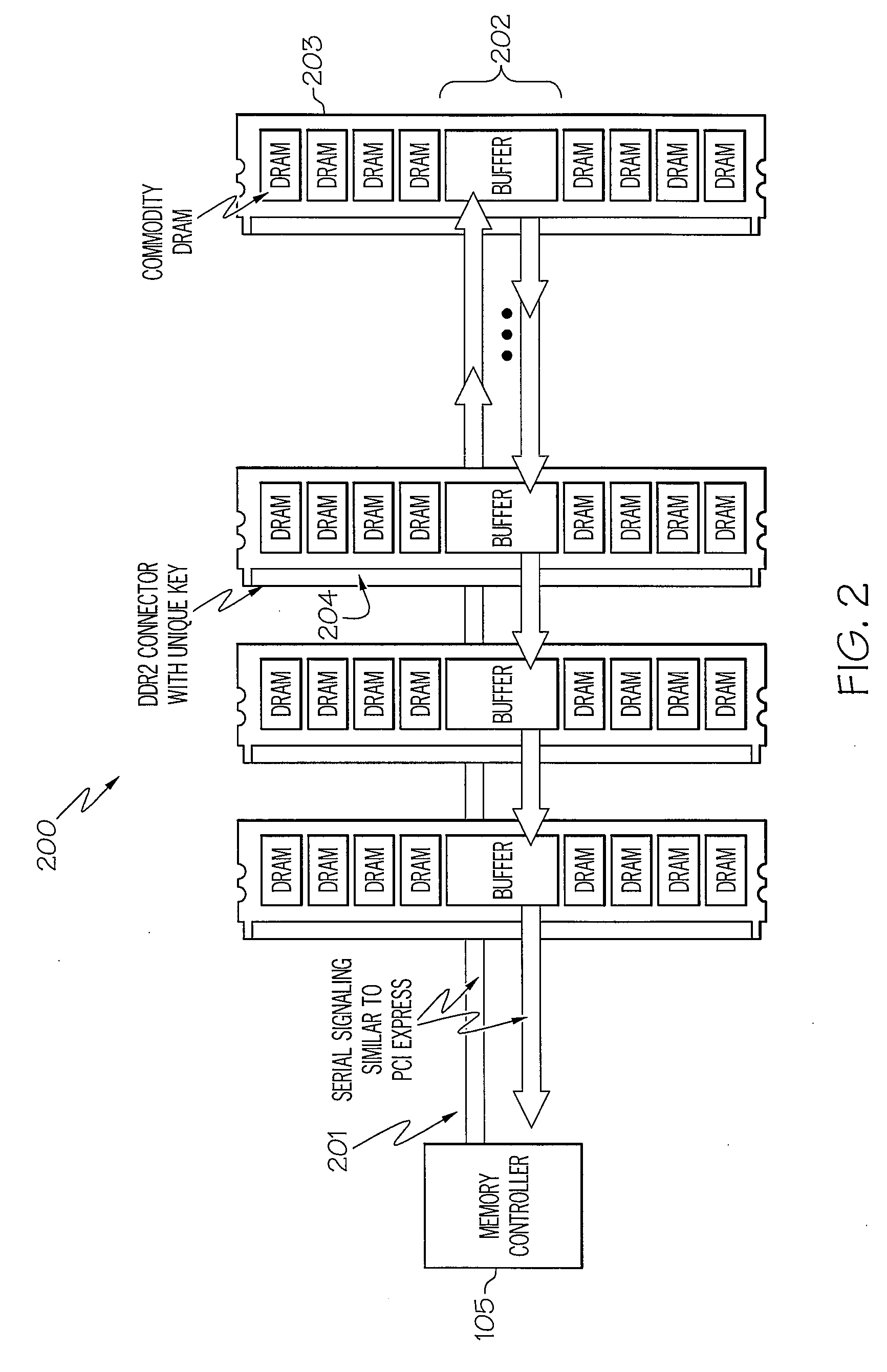
BACKGROUND OF THE INVENTION[0001]1. Technical Field[0002]The present invention generally relates to computer memory systems and in particular to accessing data in computer memory systems. Still more particularly, the present invention relates to scheduling access to memory data within computer memory systems.[0003]2. Description of the Related Art[0004]In a data processing system, requests for data stored within memory (memory data) are received by a memory controller, which controls access to the memory data. In a Fully Buffered Dual Inline Memory Module (FBDIMM) memory subsystem, when a particular data item is requested through the memory controller, a command packet is sent (via serial signaling) down a chain of buffer modules until the packet reaches a buffer chip that is connected to the Dynamic Random Access Memory (DRAM) chips that contains the requested data.[0005]The buffer modules are often interconnected via a parallel Double Data Rate (DDR)-based interface. The buffer ch...

Claims


Application Information

Patent Timeline
IPC IPC(8): G06F12/00
CPCG06F13/4243
Inventor ALLEN, JAMES J.JENKINS, STEVEN K.TROMBLEY, MICHAEL R.
Owner GLOBALFOUNDRIES INC
Learn More