Supine patient support for medical imaging

a patient support and medical imaging technology, applied in the field of patient beds, can solve the problems of affecting the patient's health, affecting the operation of the patient, and unable to easily control the procedure,

Active Publication Date: 2008-09-11
INVIVO CORP
View PDF88 Cites 57 Cited by
  • Summary
  • Abstract
  • Description
  • Claims
  • Application Information

AI Technical Summary

Benefits of technology

The present technology provides a stretcher that can be used in medical imaging and intervention procedures. The stretcher is made of materials that are compatible with imaging and has an opening that matches the gap between the table and the stretcher. The stretcher can be used as a replacement for a general-purpose patient support stretcher or can provide clearance for a non-removable stretcher. The table can also have patient immobilizing attachments for positioning the patient in a stable position during imaging and intervention procedures. These attachments include straps, belts, and a head rest to further stabilize the patient.

Problems solved by technology

The patent text describes a technical problem in the field of medical imaging, where there is a need for a patient bed that allows access to the lower body for imaging and intervention procedures. Current patient beds used for imaging have limitations in providing access to patient tissues, which can affect the quality and reliability of results. The patent aims to address this problem by providing a patient bed that allows for better access and line-of-sight for specialized devices used in image-guided intervention.

Method used


Image

  • Supine patient support for medical imaging
  • Supine patient support for medical imaging
  • Supine patient support for medical imaging

Examples


Embodiment Construction

)

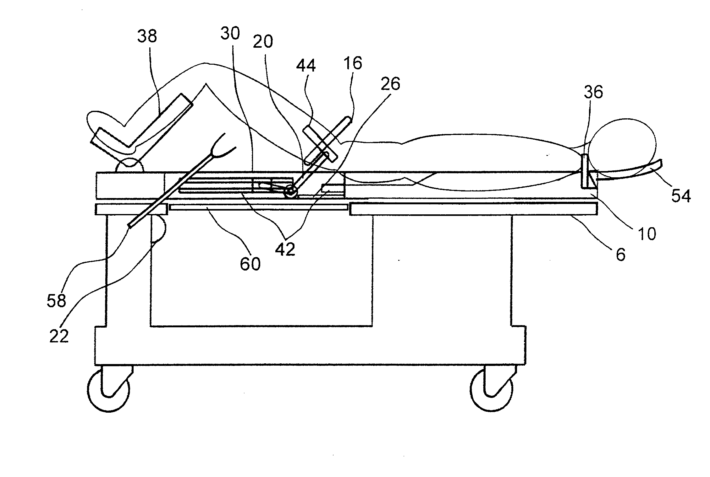
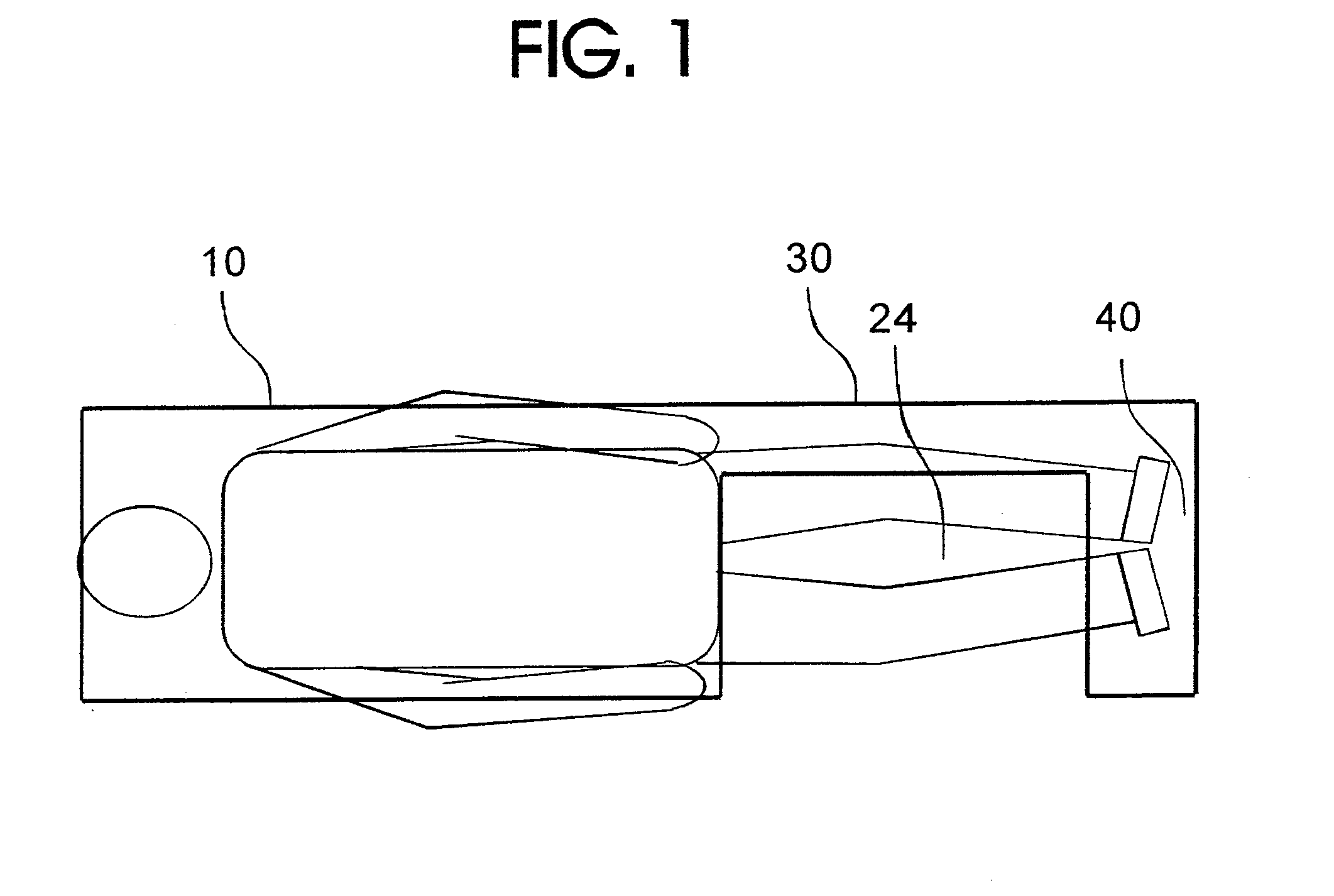
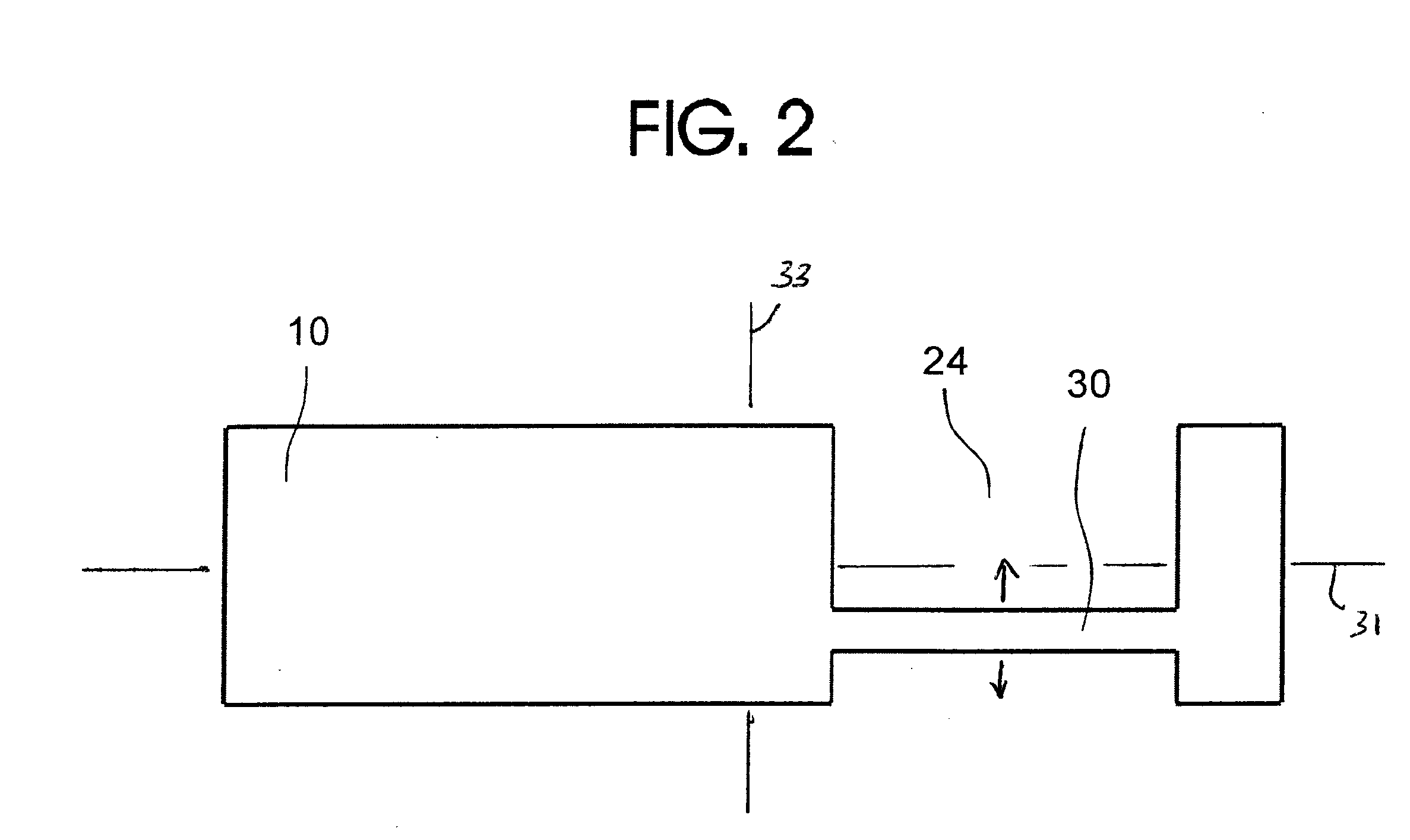
[0029]A medical imaging system or imager 2, such as shown in FIGS. 6-8, has an aperture, opening, window or other accessible volume or area 28 which in turn contains or leads into an imaging volume 4 into which a patient is moved during an imaging procedure. The data acquired by the imager 2 is used to create a two- or three-dimensional image of the organ or area of interest of the patient being examined. In accordance with the present invention, a movable stretcher 6 which may have an elevating portion is used initially to support a tabletop 10 which in turn supports a supine patient who may eventually be advanced, along with the tabletop 10 into the imaging volume 4.

[0030]During an imaging or interventional procedure, a physician, technician or other operator of the imaging device may position a number of devices inside the tissues which are under examination. This may include biopsy needles, biopsy needle guides 16 and trans-rectal MR imaging coils 18, as shown in FIGS. 4 and 5....


PUM


Abstract

A patient supporting apparatus used in medical imaging technologies has an inventive tabletop and stretcher system. The tabletop has a gap or narrowing of prescribed location and size, for example, more than thirty percent of the width of the tabletop is removed inferior to the patient's pelvis within a region of at least 0.3 meters in length. The stretcher supports the tabletop and includes a gap or narrowing so that the access of the operator's hand, arm, and line of sight is not obstructed from the gap or narrowing of the tabletop.

Description


Claims


Application Information

Patent Timeline
Owner INVIVO CORP
Why Eureka
Try Eureka