Die Holder Technology for Metal-Fabricating Press

a technology of metal-fabricating presses and die holders, which is applied in the direction of forging/pressing/hammering apparatus, shaping tools, instruments, etc., can solve the problems of additional difficulty, dies that are difficult to remove from the die holders, and the process of replacing dies is difficult and time-consuming

Active Publication Date: 2008-09-11
WILSON TOOL INT
View PDF50 Cites 12 Cited by
  • Summary
  • Abstract
  • Description
  • Claims
  • Application Information

AI Technical Summary

Benefits of technology

[0004]In some embodiments, the die holder has an open configuration that involves a side of the die holder being open. Such die holders are useful, for example, for mounting and dismounting dies in a confined space, such as between the upper and lower tables of a press. Such die holders can be configured to allow a die to be easily inserted in, or removed from, the die holder from the perimeter of the press. This may avoid the need of having to lift a die upwardly during removal from the die holder, which may be difficult due to the limited space between the tables of the press.
[0009]In some embodiments, the invention provides a die holder having a die-release mechanism. The die-release mechanism can include a body with a contact portion adapted to contact a portion of the die to apply a separation force on the die to urge the die away from at least a portion of the die holder. Such a die-release mechanism may, for example, be useful for overcoming stiction and facilitating removal of the die from the die holder.

Problems solved by technology

Thus, replacing dies can be a difficult and time consuming process.
In addition, after a pressing operation, the die can be hard to remove from the die holder due to stiction.
Stiction occurs when the die becomes stubbornly stuck in the die holder (e.g., due to a close fit between the die and the die holder, and any lubrication present).
Stiction causes additional difficulty because the die must be forced from the die holder.

Method used


Image

  • Die Holder Technology for Metal-Fabricating Press
  • Die Holder Technology for Metal-Fabricating Press
  • Die Holder Technology for Metal-Fabricating Press

Examples


Embodiment Construction

[0053]The following detailed description is to be read with reference to the drawings, in which like elements in different drawings have like reference numerals. The drawings, which are not necessarily to scale, depict selected embodiments and are not intended to limit the scope of the invention. Skilled artisans will recognize that the given examples have many useful alternatives, which fall within the scope of the invention.

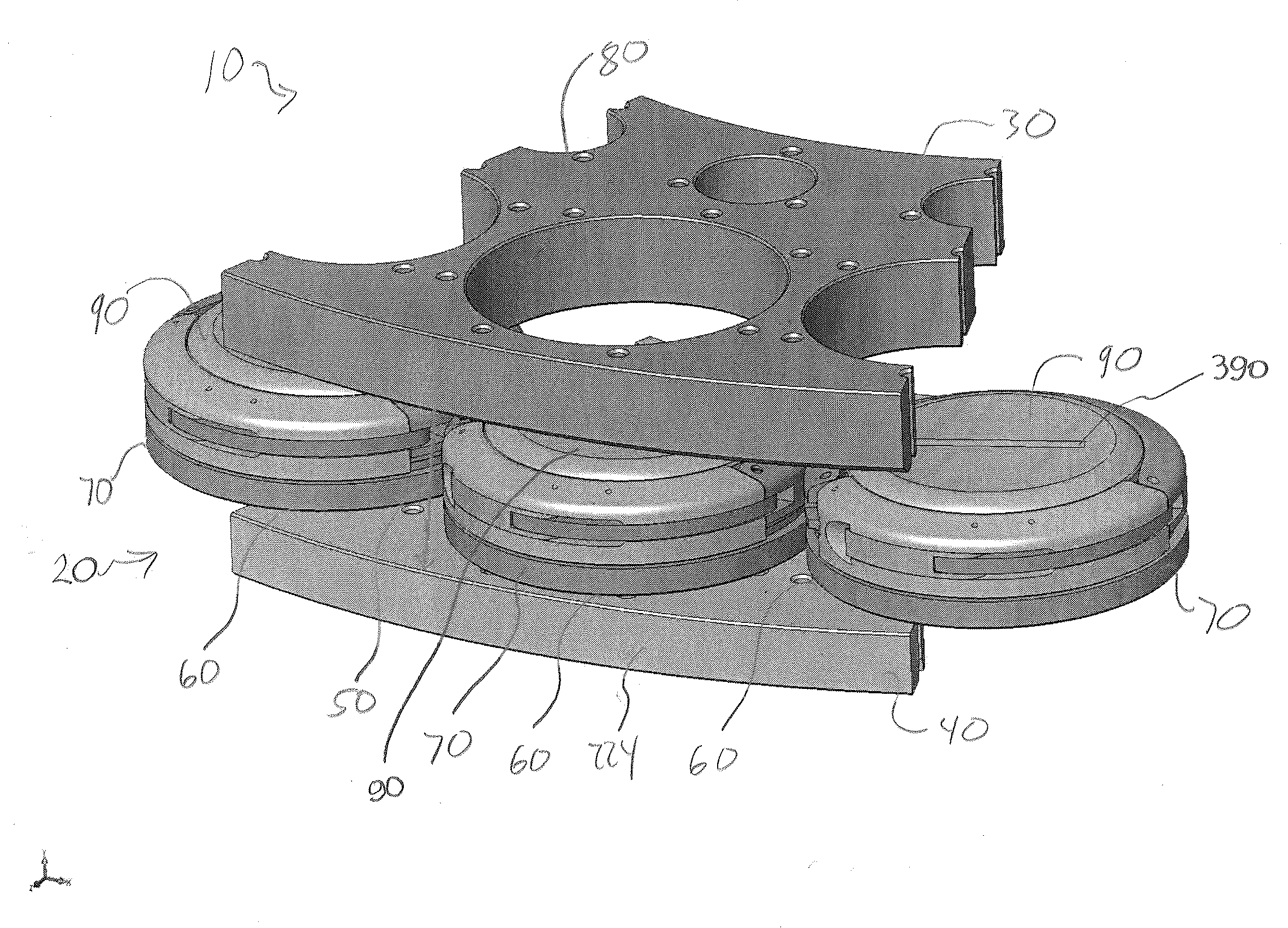
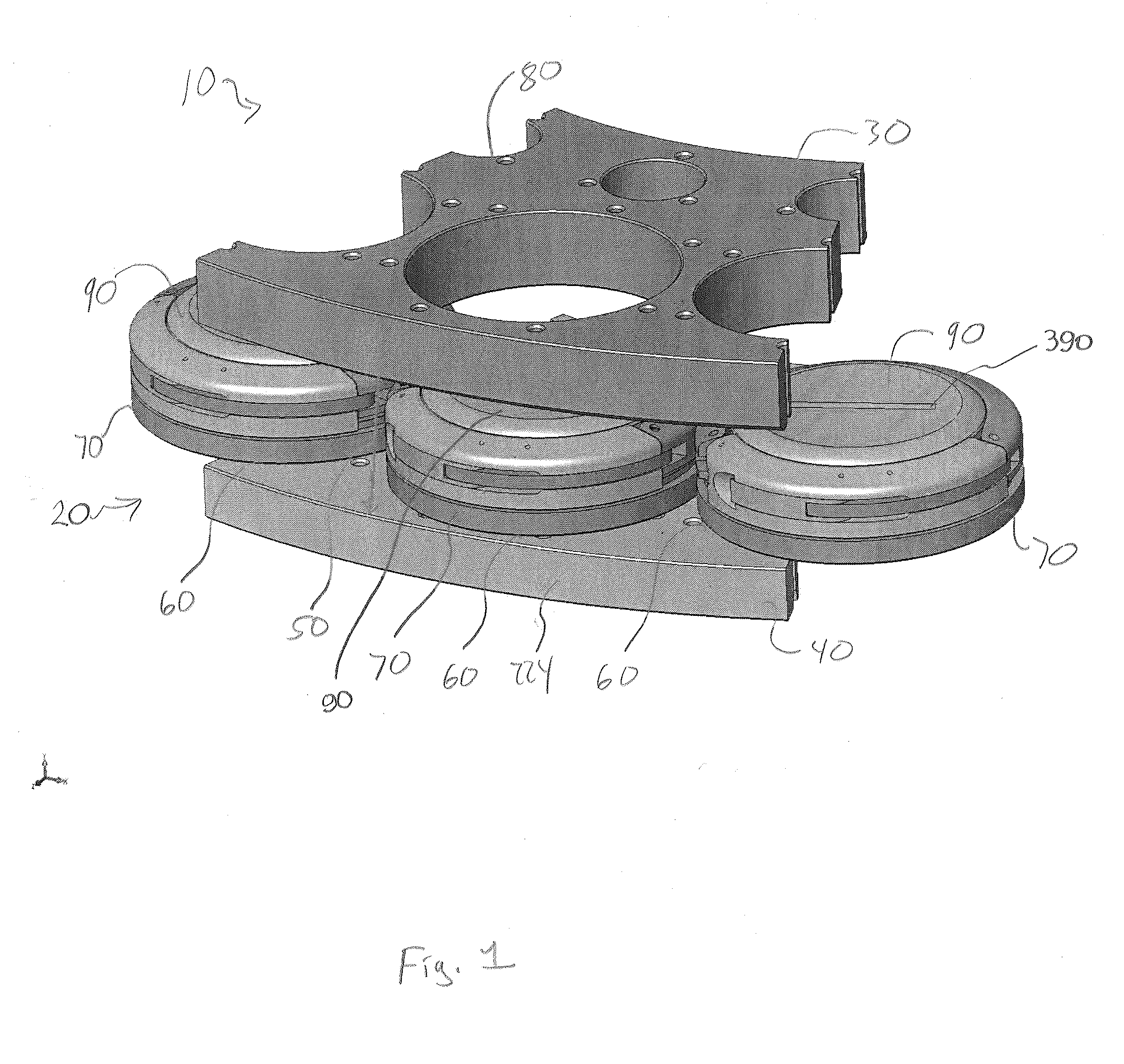
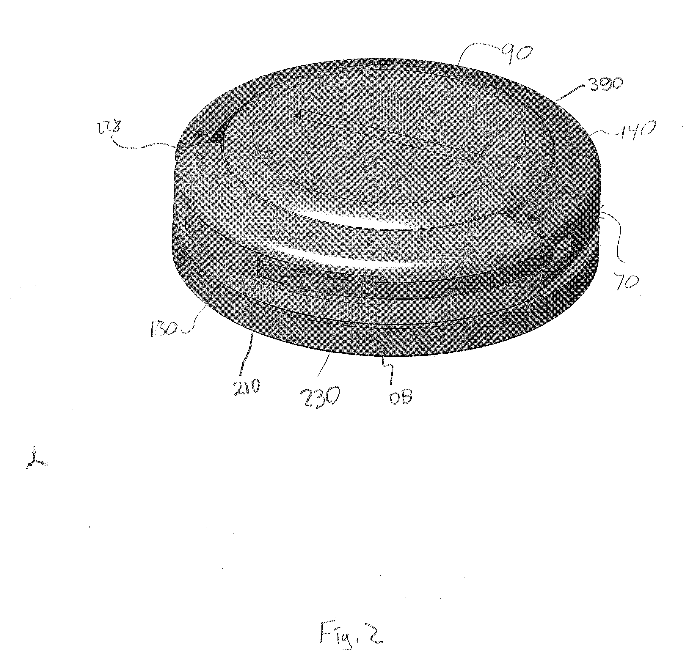
[0054]Some embodiments of the invention provide a die holder for a metal-fabricating press. In some cases, the press has an upper table and a lower table. A gap between the upper and lower tables is adapted to receive sheet metal or another sheet-like workpiece. In some cases, the upper table may be omitted. The lower table preferably is adapted to have mounted thereon at least one die holder (a wall portion 140 of the die holder may be mounted fixedly on the table, and a clamp portion 130 of the die holder may, in some cases, be adapted for being removably att...


PUM

PropertyMeasurementUnit
depthaaaaaaaaaa
depthaaaaaaaaaa
depthaaaaaaaaaa

Abstract

The invention involves a die holder for a press, such as a metal-fabricating press. The die holder can be configured to receive a die, and can include a clamp portion and a wall portion. Preferably, the clamp and wall portions can be positioned in an open configuration or a closed configuration, and the die holder can be adjusted from an unclamped configuration to a clamped configuration. The die holder may have a die-release mechanism useful for overcoming stiction and facilitating removal of the die from the die holder.

Description

FIELD OF THE INVENTION[0001]The present invention is in the field of die holders for machine tools. More particularly, this invention relates to die holders for metal-fabricating presses.BACKGROUND OF THE INVENTION[0002]Metal-fabricating presses, such as turret presses, single-station presses, etc., are used to fabricate sheet metal and other sheet-like workpieces. Commonly, each press includes an upper table and a lower table, and at least one die holder adapted for holding a die securely between the upper and lower tables. In many cases, the die holder is adapted to tightly hold the die with a plurality of set screws. In order to change out a die, the set screws must be loosened before the old die can be removed. Then, the new die can be loaded into the die holder (e.g., after moving the new die into the space between the upper and lower tables). The upper and lower tables of many presses are relatively close together. Thus, replacing dies can be a difficult and time consuming pro...

Claims


Application Information

Patent Timeline
Patent Type & Authority Applications(United States)
IPC IPC(8): B21D37/00
CPCB21D37/04Y10T29/5168Y10T483/1736B21D37/14Y10T83/8732Y10T83/8748Y10T83/9457Y10T83/9488
Inventor SHIMOTA, JON M.LEE, BRIAN J.
Owner WILSON TOOL INT
Why Eureka
Try Eureka