Fireman's Rescue Tool

a rescue tool and hand-held technology, applied in the field of hand-held tools, can solve the problems of overkill and ineffective types of tools, severe injuries or even death to victims and rescuers, and ineffective use of conventional hammers in such situations

Inactive Publication Date: 2008-09-11
BRACKBILL BRIAN D +1
View PDF20 Cites 5 Cited by
  • Summary
  • Abstract
  • Description
  • Claims
  • Application Information

AI Technical Summary

Benefits of technology

[0012]The sheet member comprises a handle portion having a finger grip section and a rear section. The finger grip section is adapted for gripping by the person's fingers, and the rear section is adapted for gripping by the person's palm. Preferably, the handle portion further includes a flared base section, which further aids in grasping of the tool by the person.

Problems solved by technology

Yet for separating smaller items, such as interior trim, plastic, upholstery or headliners, these types of tools are overkill and ineffective and have the capability of cutting into the pressurized airbag inflation cylinder concealed behind some interior trim materials.
If the pressurized cylinder were breached, it would explode and fragment, possibly severely injuring or even causing death, to both the victims and rescuers alike.
For example, a conventional hammer is not effective in such situations due to its size and inability to easily tear through roofing materials or upholstery.
Further, a hammer does not protect the hand of the user in any way from shards of glass or other sharp debris that may be in the hand's travel path when swinging such a device.
Such a tool, while more effective than a conventional hammer, does not provide finger or hand protection to the user.
Further, such a device is made of several parts that must be assembled, and as such is considerably more expensive to manufacture than a tool stamped or cut out of a single piece of sheet metal stock.

Method used


Image

  • Fireman's Rescue Tool
  • Fireman's Rescue Tool
  • Fireman's Rescue Tool

Examples


Embodiment Construction

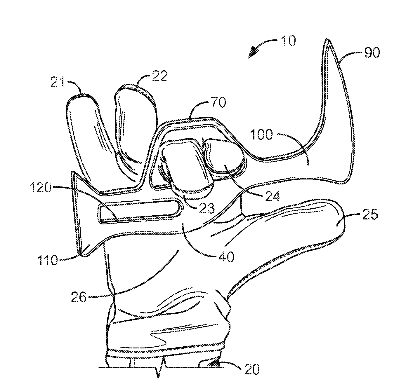
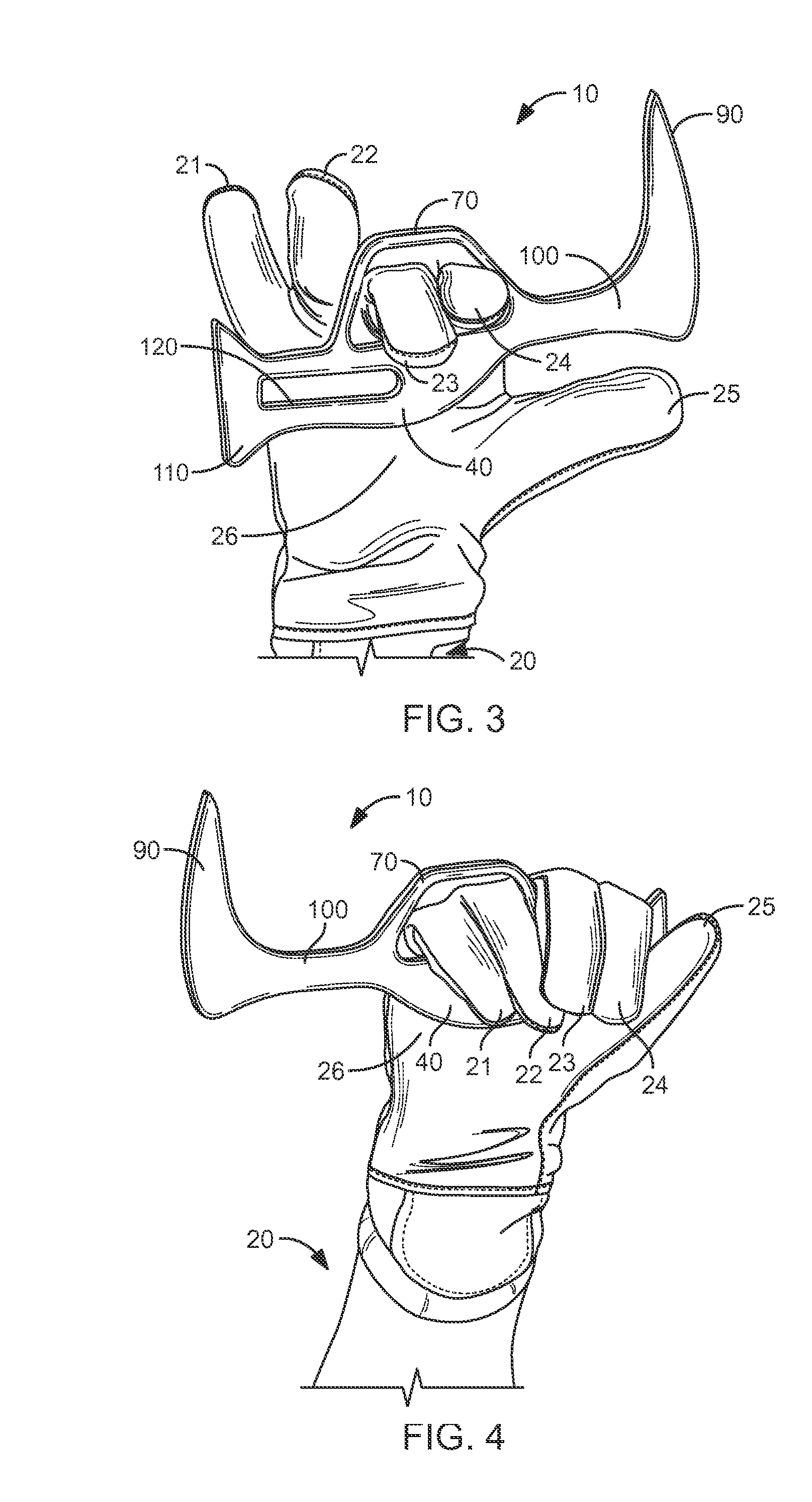
[0023]The present invention, illustrated in FIGS. 1 and 3, is directed towards a hand tool 10 for use by a person 20, such as a firefighters Such a tool can be used to pry upholstery away from a vehicle frame (not shown), aid in the breaking and removal of a windshield (not shown), or the like. Further, the tool 10 may be quickly and easily stored and retrieved from the firefighter's PPE turnout pockets, located in the jacket or pants section thereof.

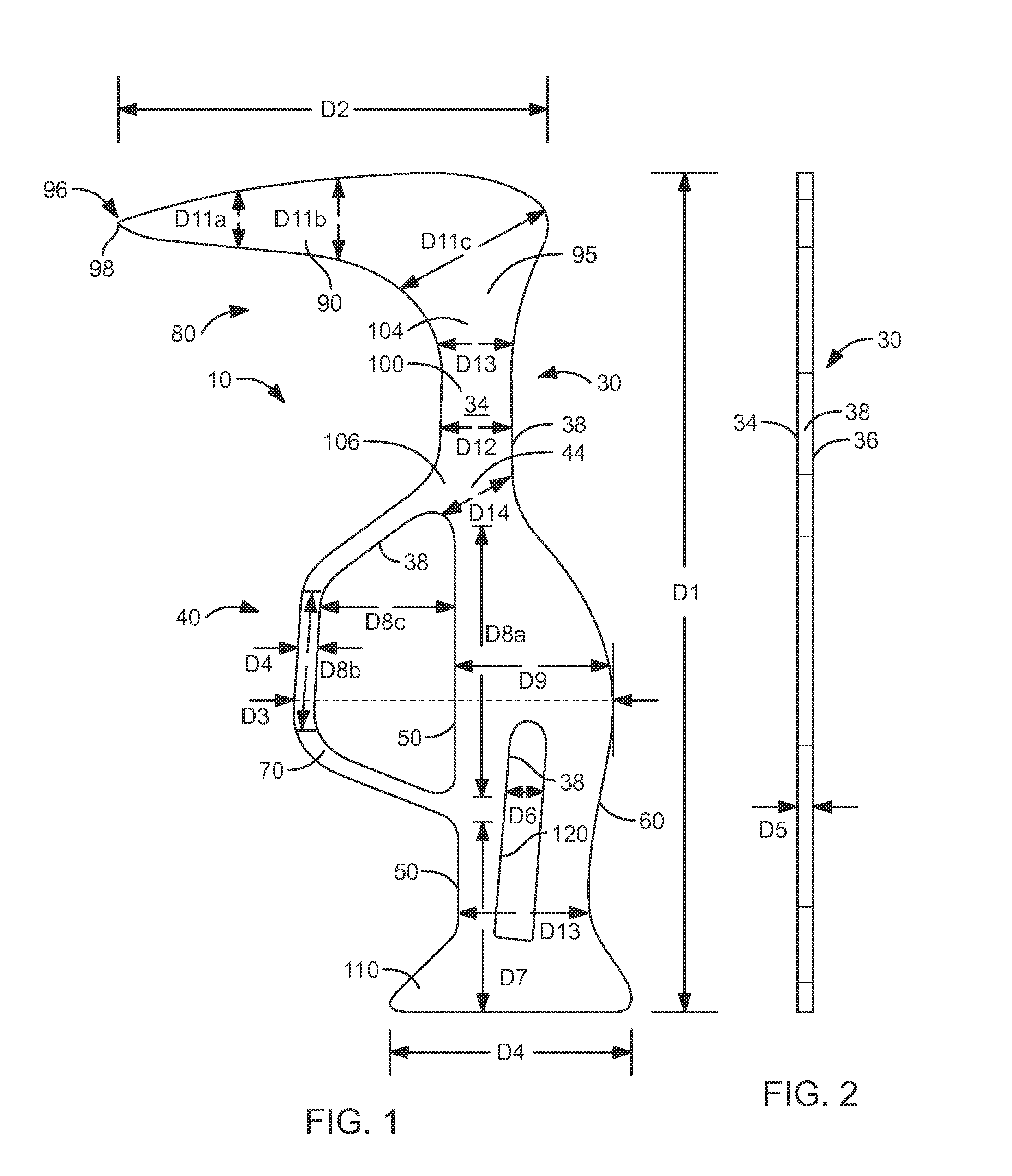
[0024]The hand tool 10 of the present invention comprises a unitary sheet member 30 having a substantially flat top side 34 and bottom side 36, each mutually connected by at least one peripheral edge 38. Preferably the sheet member 30 is made from a metallic sheet material which can be stamped or cut with, for example, a laser cutting process. Alternately, the tool 10 may be cast from iron or other molten metals or alloys.

[0025]The sheet member 30 comprises a handle portion 40 having a finger grip section 50 and a rear section 60. The f...


PUM


Abstract

A hand tool for use by a person, such as a firefighter, is disclosed. The hand tool of the present invention comprises a unitary sheet member having a substantially flat top side and bottom side, each mutually connected by at least one peripheral edge. The sheet member comprises a handle portion having a finger grip section and a rear section. The finger grip section is adapted for gripping by the person's fingers, and the rear section is adapted for gripping by the person's palm. The finger grip section includes a first finger guard at least partially therearound for protecting at least two of the person's fingers, depending upon how the person holds the tool. A hook portion has a hook fixed at a hook base proximate to a top section of a neck. The neck is fixed at a bottom section thereof to a top section of the handle portion. A tip of the hook may be formed into a regular screwdriver. Further, pivot notches may be formed in the peripheral edge proximate the tip of the hook. A gas shut-off aperture may be formed into the handle portion, the aperture for fitting around a gas valve and the sheet member rotated around the gas valve for shutting off same.

Description

CROSS-REFERENCE TO RELATED APPLICATIONS[0001]Not Applicable.STATEMENT REGARDING FEDERALLY SPONSORED RESEARCH AND DEVELOPMENT[0002]Not Applicable.FIELD OF THE INVENTION[0003]This invention relates to hand tools, and more particularly to a fireman's hand tool for aiding in rescuing activities.DISCUSSION OF RELATED ART[0004]Rescue workers, and firefighters in particular, sometimes need to aid those trapped in vehicles. Tools such as the so-called “jaws of life” and other pneumatic or hydraulic tools are known for cutting metal, prying doors open and otherwise serving to separate objects in order to rescue those trapped therebetween. Yet for separating smaller items, such as interior trim, plastic, upholstery or headliners, these types of tools are overkill and ineffective and have the capability of cutting into the pressurized airbag inflation cylinder concealed behind some interior trim materials.[0005]To prevent any additional injury to the accident victim or injury to the rescuer, i...

Claims


Application Information

Patent Timeline
Patent Type & Authority Applications(United States)
IPC IPC(8): B25B28/00
CPCB25B15/00A62B3/005
Inventor BRACKBILL, BRIAN D.BRACKBILL, ROBERT B.
Owner BRACKBILL BRIAN D
Why Eureka
Try Eureka