Process for pressure actuation of a shifting element

a technology of shifting element and pressure actuation, which is applied in the direction of mechanical equipment, clutches, instruments, etc., can solve the problems of negative influence on shifting quality, and achieve the effect of increasing or improving the accuracy of leakage amount compensation for non-actuated shifting elements

a technology of shifting element and pressure actuation, which is applied in the direction of mechanical equipment, clutches, instruments, etc., can solve the problems of negative influence on shifting quality, and achieve the effect of increasing or improving the accuracy of leakage amount compensation for non-actuated shifting elements

US20080217134A1Inactive Publication Date: 2008-09-11ZF FRIEDRICHSHAFEN AG

Image

  • Process for pressure actuation of a shifting element
  • Process for pressure actuation of a shifting element

Examples


Embodiment Construction

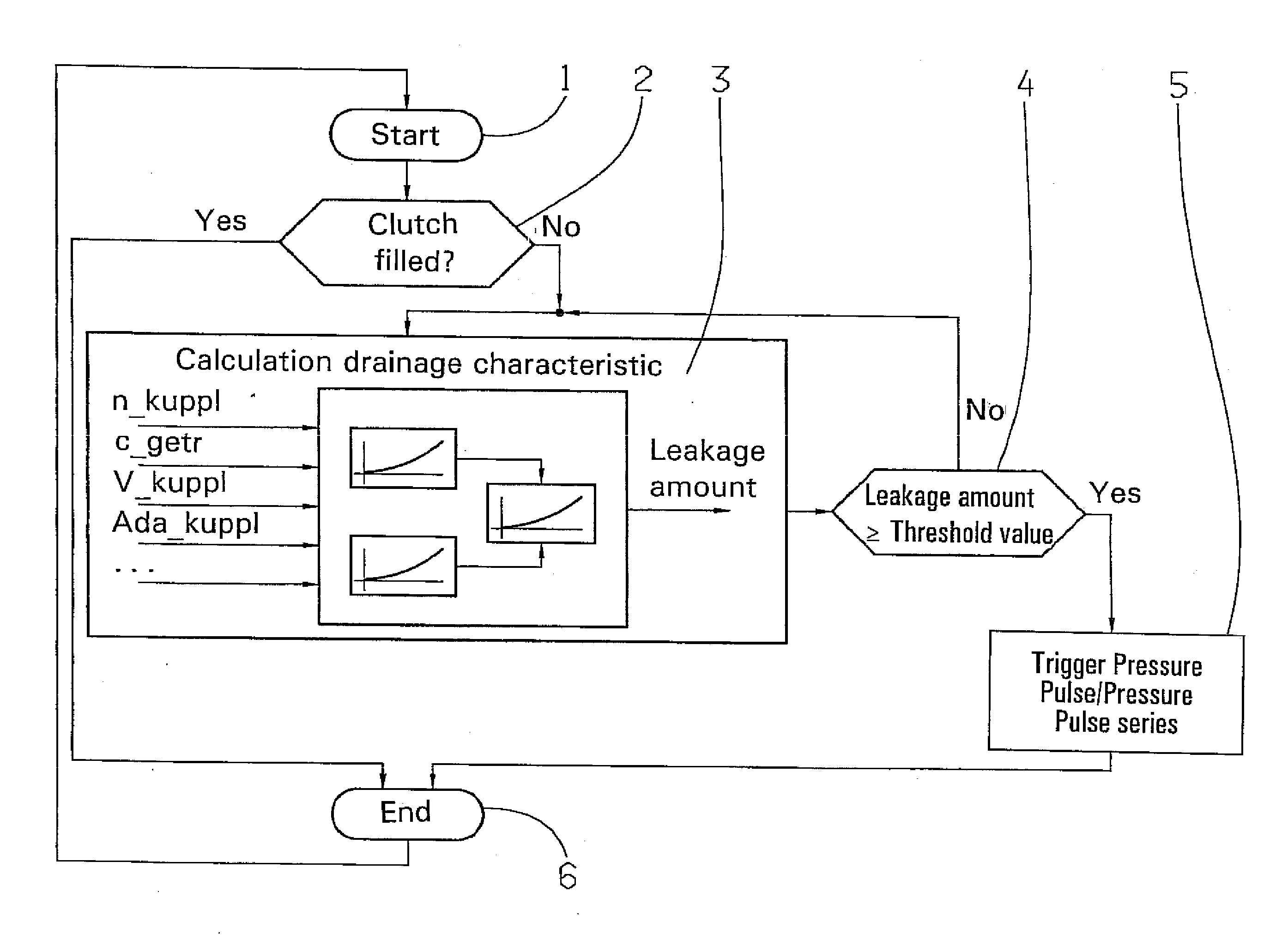
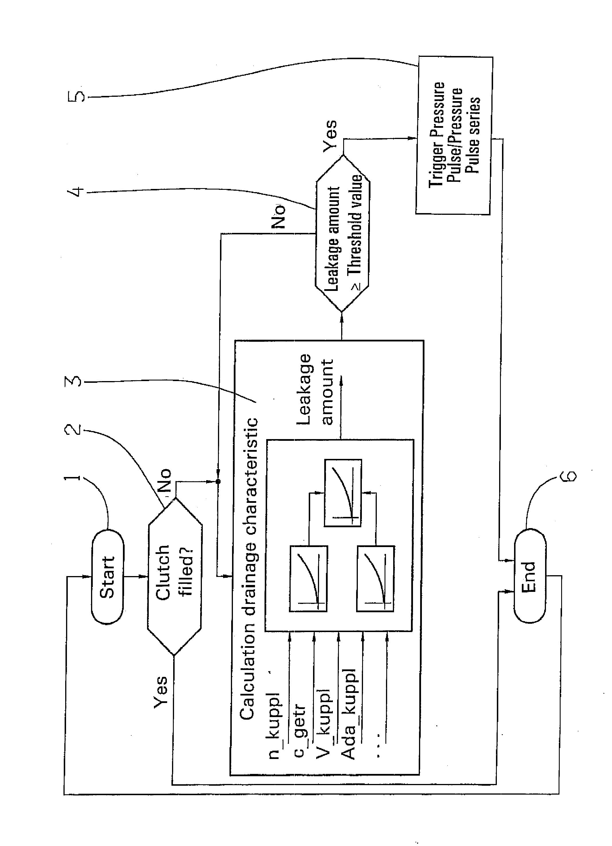
[0034]A first program step 1, the function is started. A second program step 2 tests to see if a disk clutch, which is to be actuated in the de-activated state, if needed, with a pressure medium pulse for leakage compensation outside of a gear shifting, is currently filled with pressure medium. The piston chamber of the clutch is always filled with pressure medium when the latter is activated (that is, engaged and transferring torque). The piston chamber of the clutch can, however, also be filled with pressure medium in the de-activated state (that is, unengaged and not transferring torque) by maintaining a defined low pressure in the piston chamber, which is known from the state of the art as prefilling, and serves to keep the piston of the de-activated (that is, not transferring torque) clutch in a piston position close to the disk set of the clutch in order to shorten the reaction time between the shifting command and actual torque transfer during a subsequent engagement of the c...


PUM


Abstract

The invention concerns a process for pressure actuation of a rotating shifting element of an automatic transmission or automated manual transmission, in which the shifting element is configured with a piston that interacts with a torque transfer element and a pressure medium supply, by way of which the piston can be actuated with pressure medium in order to be displaced into a positioned defined for an activated state of the shifting element, and in which a pressure pulse can be induced in the pressure medium supply in a de-activated state of the shifting element. It is proposed that the pressure medium pulse be triggered when the pressure medium amount drained from the de-activated shifting element has reached a predefined value.

Description

[0001]This application claims priority from German Application Serial No. 10 2007 010 942.5 filed Mar. 7, 2007.FIELD OF THE INVENTION[0002]The invention concerns a process for pressure actuation of at least one rotating shifting element of an automatic transmission or automated manual transmission.BACKGROUND OF THE INVENTION[0003]Automatic powershift transmissions containing planetary gearsets with clutches and brakes, which make shifting of gears under load possible, are sufficiently known from practice. In order to initiate a gear change, the friction shifting elements (clutches or brakes) are usually hydraulically actuated with pressure. Friction shifting elements configured as a disk clutch or disk brake usually have a piston which, when actuated by pressure, compresses the disk set. The shifting element can transfer the torque in a friction-locked manner induced in the shifting element. The filling of the piston chamber of the shifting element with pressure medium or the pressu...

Claims


Application Information

Patent Timeline
11 Sep 2008
Publication
US20080217134A1
IPC
F16D25/00; G06F19/00
CPC
F16H2061/062; F16H61/061
Inventors
POPP, CHRISTIAN; STEINHAUSER, KLAUS