Combination physical separator and filter device to remove contaminants from stormwater runoff

a technology of filter device and separator, which is applied in the direction of liquid displacement, multi-stage water/sewage treatment, separation process, etc., can solve the problems of severe degradation of our watershed, accumulation of pollutants,

Inactive Publication Date: 2008-09-11
ADVANCED DRAINAGE SYST +1
View PDF13 Cites 37 Cited by
  • Summary
  • Abstract
  • Description
  • Claims
  • Application Information

AI Technical Summary

Benefits of technology

[0003]When runoff water is cleaned, according to the present invention, there are three levels of flow. The first of the three levels is herein referred to as low flow. This level of flow involves a substantial cleaning by any suitable cleaning metho...

Problems solved by technology

Since these impervious surfaces typically have vehicles or traffic on them, an accumulation o...

Method used


Image

  • Combination physical separator and filter device to remove contaminants from stormwater runoff
  • Combination physical separator and filter device to remove contaminants from stormwater runoff
  • Combination physical separator and filter device to remove contaminants from stormwater runoff

Examples


Embodiment Construction

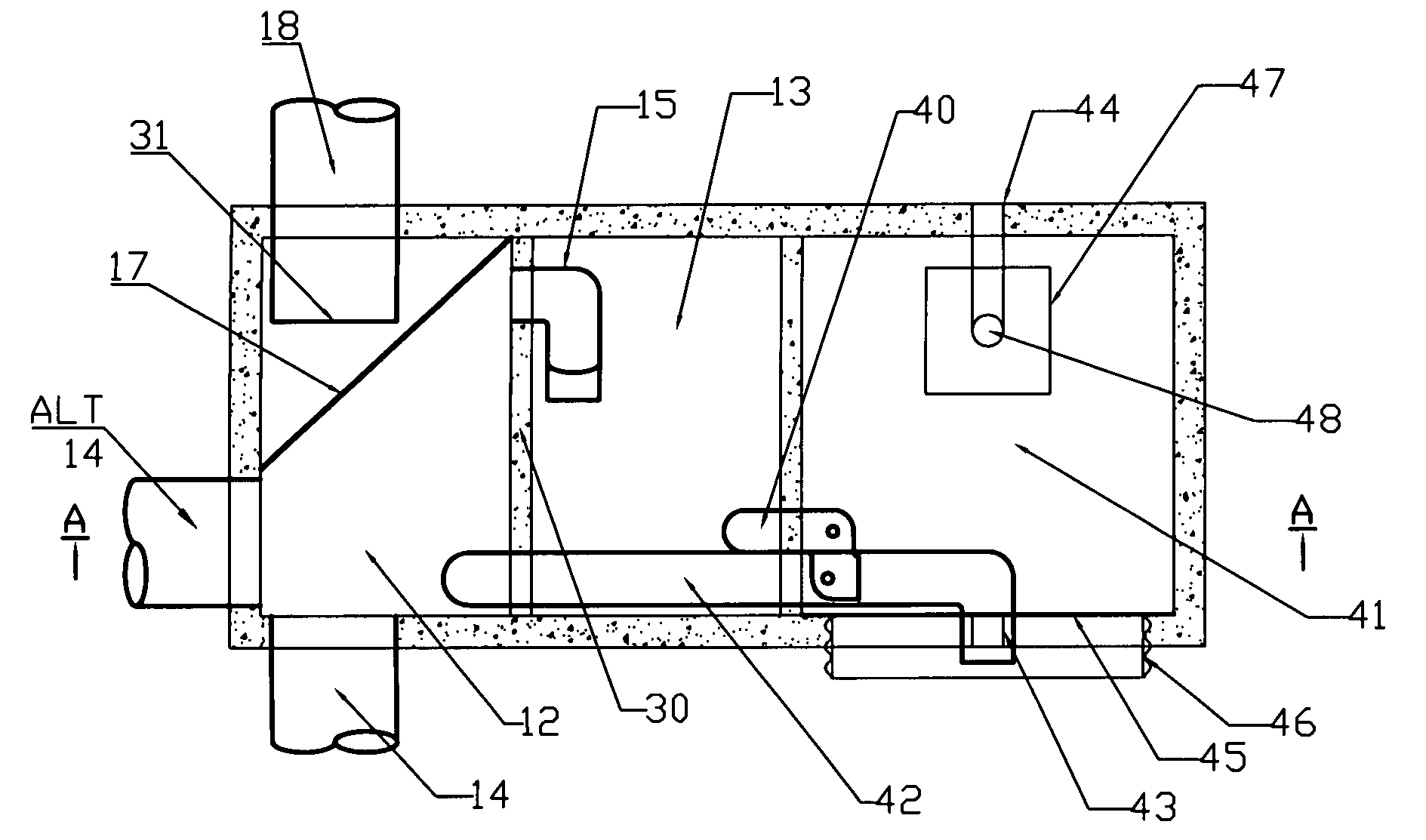
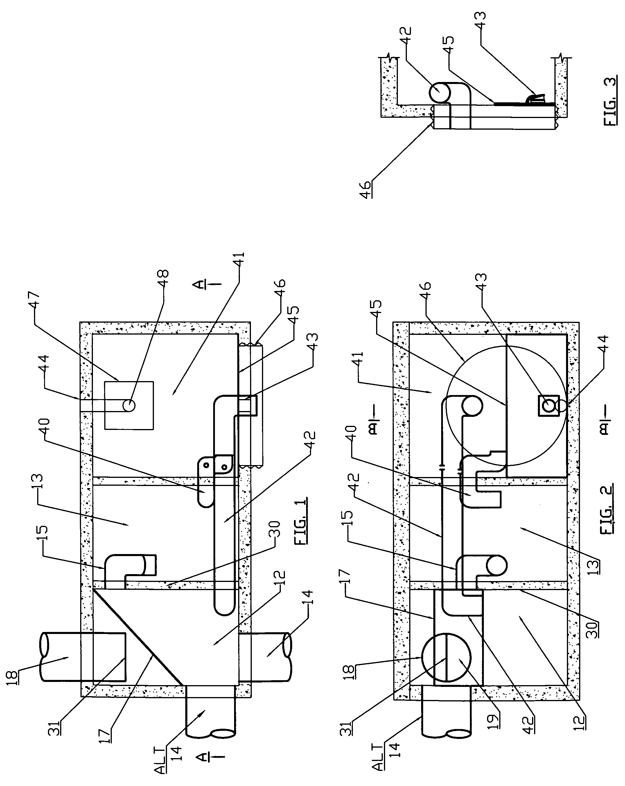
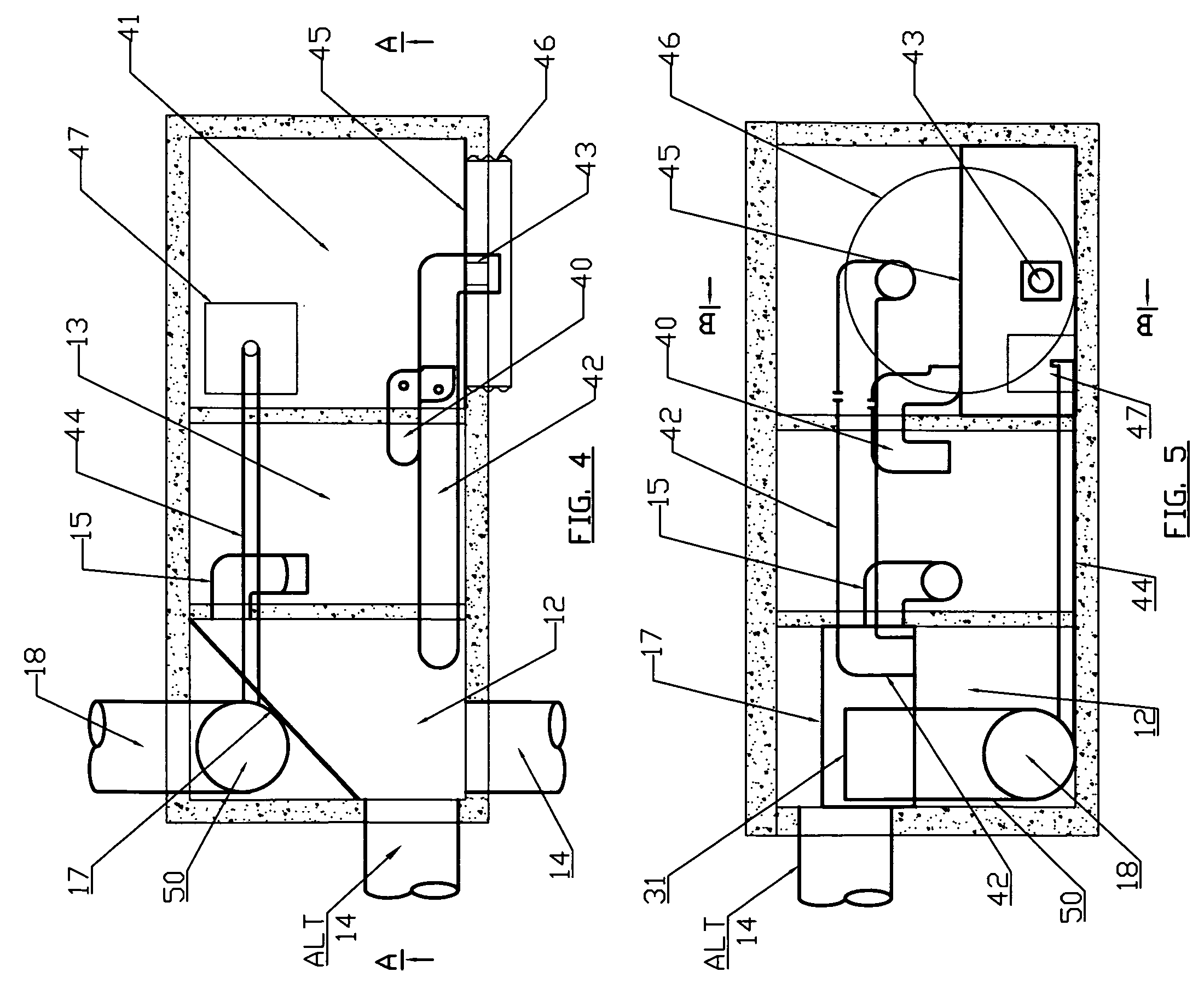
[0016]During low flow conditions, influent water enters the device through the inlet pipe 14 from which it flows directly into the primary chamber 12, causing the water level in chamber 12 to rise. When the water level in the primary chamber 12 rises, water is skimmed from the surface of that chamber by a pipe 15 that penetrates the wall 30 between the two chambers 12 and 13. This pipe delivers the inflow water to the storage chamber 13, where it enters horizontally below the water surface through a 90 degree fitting in the pipe 15. When the water enters the storage chamber 13, the entrained sediments and floatables separate from the water stream—sediments settle to the structure floor and oils rise to the water surface. The additional water entering the storage chamber 13 through pipe 15 displaces clean water from the center of the column of chamber 13 and this storage outflow enters the storage chamber outlet pipe 40 and flows into the filtration chamber 41. The treated water ente...


PUM

PropertyMeasurementUnit
Flow rateaaaaaaaaaa
Gravityaaaaaaaaaa

Abstract

An input chamber receives runoff water to be cleaned. Part of the way up the chamber wall is a restricted outlet which feeds a system for cleaning the water. At a still higher elevation another opening allows runoff water to flow to an extended detention chamber. Near the top of the chamber is an outlet pipe. A vertical baffle in front of the outlet cleans water that flows under the baffle on its way to the outlet. When the incoming flow rate is very high, water passes over the baffle to the outlet.

Description

RELATED CASES[0001]I claim the benefit of (a) my prior copending provisional application Ser. No. 60 / 905,612 filed Mar. 7, 2007 and (b) my prior copending provisional application Ser. No. 60 / 905,520 filed Mar. 7, 2007.BACKGROUND OF THE INVENTION[0002]When it rains on a parking lot, a road, or other impervious surface, the water will not permeate into the ground as it once did, and instead this water will runoff and discharge directly into a stream or receiving body. Since these impervious surfaces typically have vehicles or traffic on them, an accumulation of pollutants will occur between rain events. This runoff is then concentrated because it is unable to be absorbed into the ground, and the pollutants are concentrated as well. This has caused a severe degradation of our waterhsheds. Although many technologies now exist to treat this problem, a single structure multistage treatment system has advantages of ease of maintenance, better efficiency, lower cost, and longer life.SUMMARY...

Claims


Application Information

Patent Timeline
IPC IPC(8): B01D21/34C02F1/00
CPCB01D21/0012B01D21/003B01D21/0042E03F5/14C02F2103/001C02F2307/08B01D2221/12
Inventor PANK, THOMAS E.
Owner ADVANCED DRAINAGE SYST
Why Eureka
Try Eureka