Method and Device for Separating Particles

a particle and separation technology, applied in the field of methods and devices for separating particles, can solve the problem of not being able to separate particles that were exposed to forces acting in the same direction

Inactive Publication Date: 2008-09-11
SPECTRONIC
View PDF1 Cites 90 Cited by
  • Summary
  • Abstract
  • Description
  • Claims
  • Application Information

AI Technical Summary

Problems solved by technology

However, with this method it was not possible to separate particles that were exposed

Method used


Image

  • Method and Device for Separating Particles
  • Method and Device for Separating Particles
  • Method and Device for Separating Particles

Examples


example

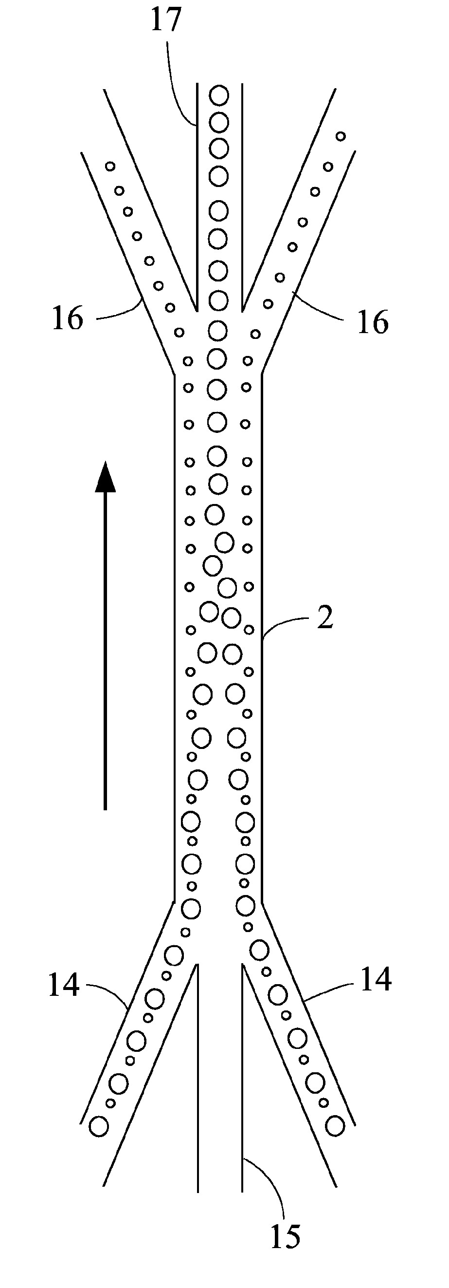
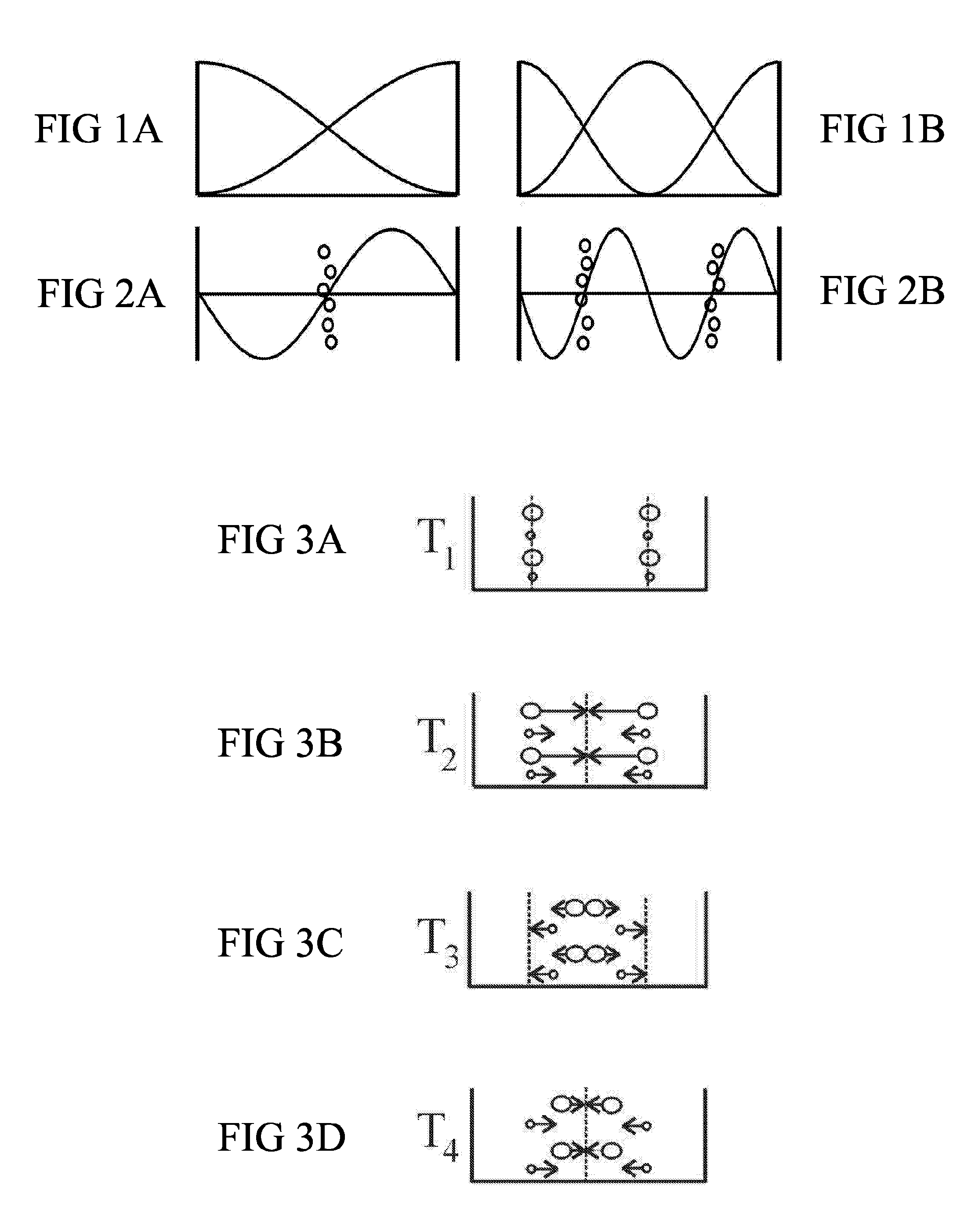
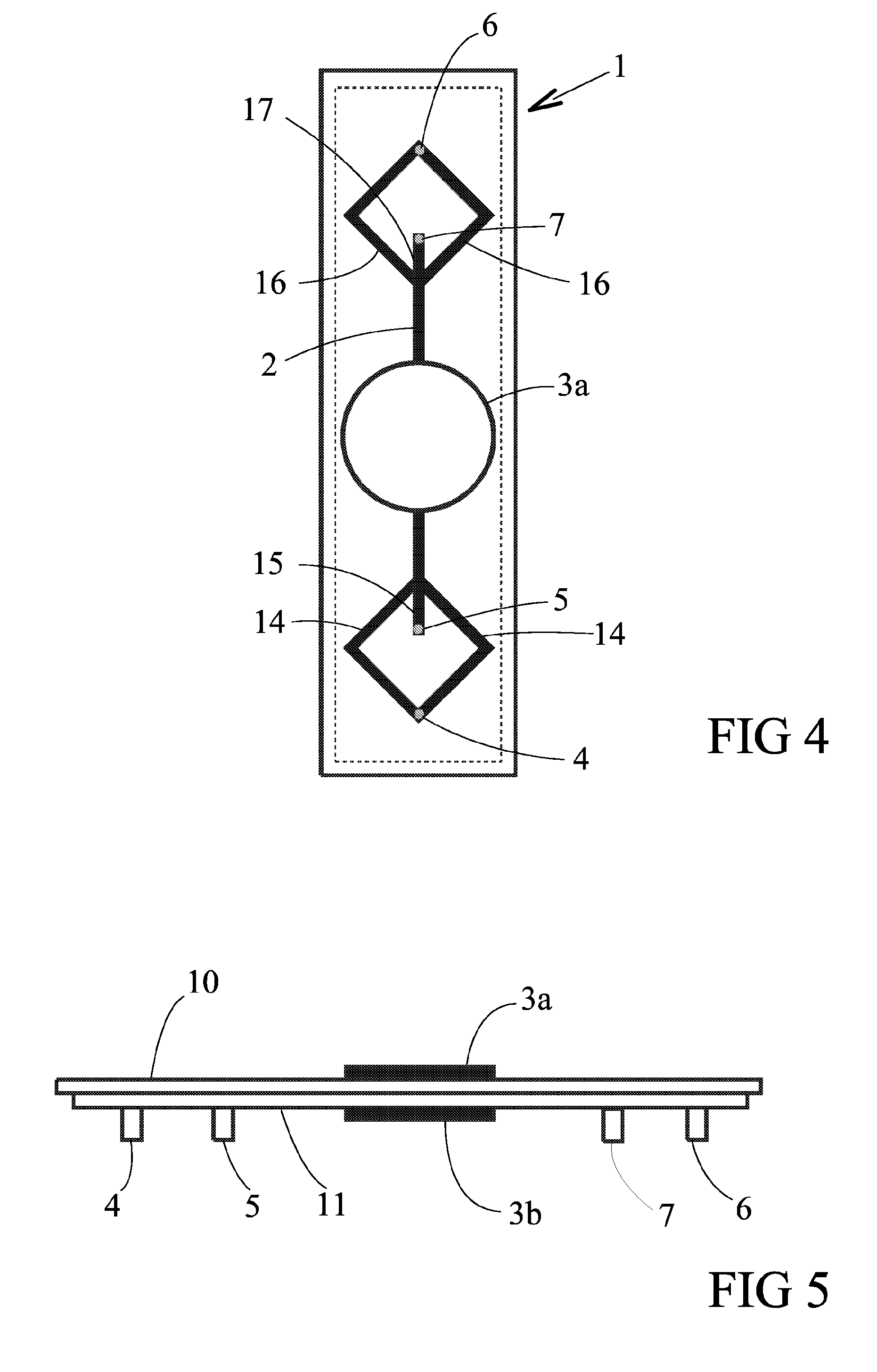
[0040]A separation channel (385 μm wide and 250 μm deep) was etched into a silicon wafer using anisotropic wet etching. The channel was sealed with a glass lid by anodic bonding and silicone tubes were glued to the inlets and outlets on the backside. The ultrasonic excitation (2 Mhz and 4 Mhz) was accomplished by attaching two piezoceramic crystals, one from the back side and one from the front side, with ultrasonic gel. The flow was controlled using three syringe pumps, 26 μl / min at the water inlet, 15 μl / min at the centre outlet and 75 μl / min at the side outlets. The balancing flow, 64 μl / min of particle solution, was self-drawn from an open cup. The particle solution consisted of a mix of 3 μm polystyrene beads, with a density of 1.05 g / cm3, and 8 μm polymethylmethacrylate beads, with a density of 1.19 g / cm3, suspended in H20. In order to get proper separation, the switching parameters had to be tuned correctly. This was done by systematically adjusting the parameters until suff...


PUM

PropertyMeasurementUnit
Timeaaaaaaaaaa
Lengthaaaaaaaaaa
Lengthaaaaaaaaaa

Abstract

The invention relates to a method and a device for separating particles using ultrasonic standing waves which are switched between two different frequencies. A second order harmonic standing wave is used together with the fundamental standing wave. If the particles are exposed to the fundamental standing wave, the forces act to collect particles at the centre. If the particles are exposed to the second order harmonic standing wave, the forces act to collect particles at the two pressure nodes at the sides. By switching the frequency between the second order harmonic standing wave and the fundamental standing wave, particles with different properties will be exposed to different accelerations and are separated into two streams.

Description

FIELD OF INVENTION[0001]The present invention relates to a method and a device for separating particles, and more particularly separation of particles using ultrasonic standing waves which are switched between two different frequencies. Particles with different properties will be exposed to different accelerations due to acoustic radiation pressure and are separated into two streams.STATE OF THE ART[0002]The theory behind the forces acting on particles suspended in a medium in an ultrasonic standing wave has been known for some time. If a standing wave is induced into a medium where a small particle is suspended the particle will be exposed to an acoustic radiation force. The force acting on the particles is a function of the position in the channel relative to a pressure node. By combining this fact with laminar flow in microchannels, particles can be collected at and separated from the pressure nodes. In the fundamental standing wave (first order resonant frequency) the force is d...

Claims


Application Information

Patent Timeline
IPC IPC(8): C02F1/36A61M1/36B01D21/00B03C
CPCA61M1/3693Y10T436/25375B01D21/283
Inventor SIVERSSON, CARL
Owner SPECTRONIC
Why Eureka
Try Eureka