Electromagnetic fuel injection valve

a fuel injection valve and electromagnetic technology, applied in the direction of fuel injection apparatus, spraying apparatus, feeding system, etc., can solve the problems of fuel injection characteristics in disorder, distortion may propagate to the valve seat member, and generate unstable distortion, so as to improve the magnetic efficiency and stable fuel injection characteristics

Inactive Publication Date: 2008-09-11
KEIHIN CORP
View PDF7 Cites 2 Cited by
  • Summary
  • Abstract
  • Description
  • Claims
  • Application Information

AI Technical Summary

Benefits of technology

[0007]The present invention has been made in view of the above circumstances, and an object thereof is to provide an electromagnetic fuel injection valve which can exert stable fuel injection characteri

Problems solved by technology

In this press-fitting process, an imbalanced distortion is generated in the magnetic cylinder due to center deviance between the magnetic cylinder and the coil housing at the time of press-fitting operation, and the

Method used


Image

  • Electromagnetic fuel injection valve
  • Electromagnetic fuel injection valve
  • Electromagnetic fuel injection valve

Examples


Embodiment Construction

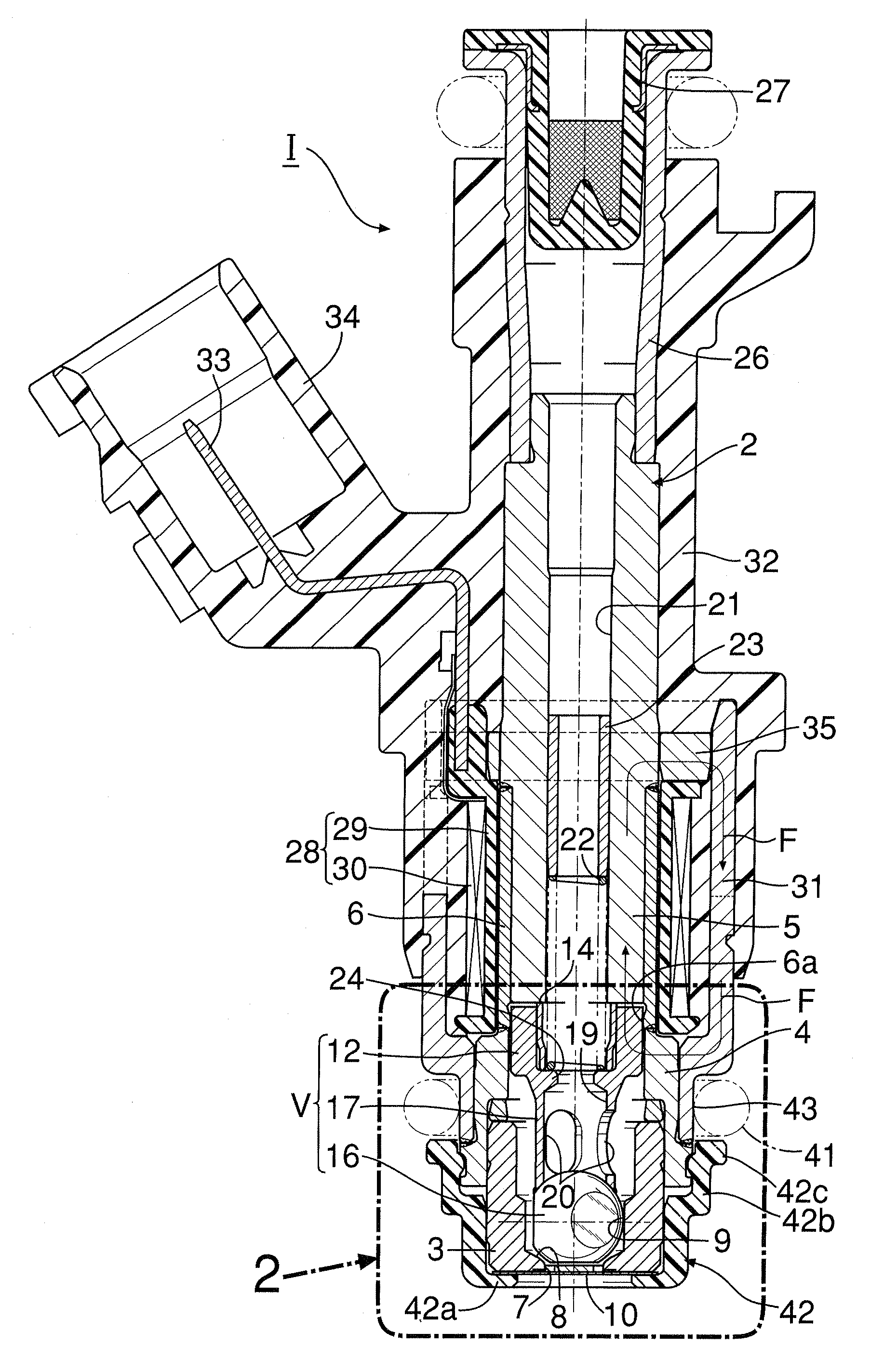
[0017]In FIG. 1, a fuel injection valve I comprises a valve housing 2 which includes: a cylindrical valve seat member 3 having a valve seat 8 at a front end thereof; a magnetic cylinder 4 press-fitted to an outer peripheral surface of a rear end of the valve seat member 3, and liquid-tightly welded thereto; a nonmagnetic collar 6 coaxially abutting on a rear end of the magnetic cylinder 4, and liquid-tightly welded thereto; a stationary core 5 fitted to an inner peripheral surface of the nonmagnetic collar 6, and welded to a rear end of the nonmagnetic collar 6; and a fuel inlet tube 26 fitted to a rear end of the stationary core 5, and liquid-tightly welded thereto.

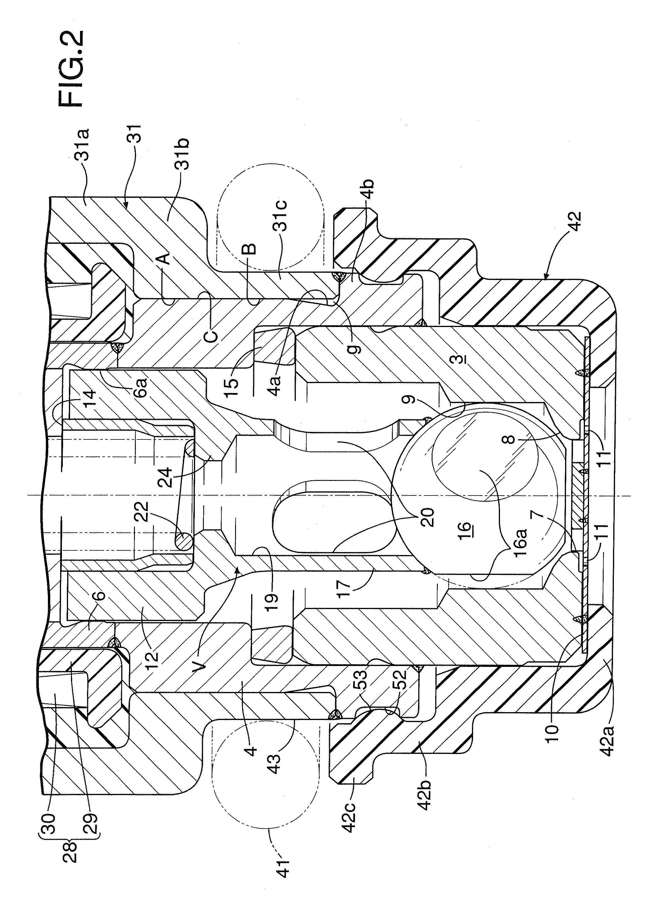
[0018]The valve seat member 3 includes a valve hole 7 penetrating a central part of a conical valve seat 8, and a cylindrical guide hole 9 leading to a rear end of the valve seat 8.

[0019]A front end portion of the nonmagnetic collar 6 that does not fit to the stationary core 5 is left as a guide portion 6a. A valve assem...


PUM


Abstract

In an electromagnetic fuel injection valve, a valve housing is formed by sequentially connecting a valve seat member, a magnetic cylinder, a nonmagnetic collar, and a stationary core. A coil housing is fittingly fixed to an outer periphery of the magnetic cylinder, and houses a coil assembly provided in an outer periphery of the stationary core. The coil housing includes a shell part surrounding the coil housing, an annular bent part bent radially inward from a front end of the shell part, and a cylindrical boss part projecting forward from a front end of the annular bent part. An inner peripheral surface of the annular bent part and an inner peripheral surface of at least a rear half part of the boss part are shrinkage-fitted to an outer peripheral surface of the magnetic cylinder. Thus, it is possible to eliminate distortion propagating to the magnetic cylinder, and eliminate a gap from fitted portions between the magnetic cylinder and the coil housing to improve magnetic efficiency, thereby exerting stabile fuel injection characteristics.

Description

RELATED APPLICATION DATA[0001]The Japanese priority application No. 2007-60254 upon which the present application is based is hereby incorporated in its entirety herein by reference.BACKGROUND OF THE INVENTION[0002]1. Field of the Invention[0003]The present invention relates to an improvement of an electromagnetic fuel injection valve comprising: a valve housing which includes: a valve seat member having a valve hole at a front end thereof, and a valve seat member leading to an inner end of the valve hole; a magnetic cylinder connected to a rear end of the valve seat member; and a stationary core connected to a rear end of the magnetic cylinder via a nonmagnetic collar; a valve element housed in the valve seat member so as to open and close the valve hole in cooperation with the valve seat; a movable core housed in the magnetic cylinder, the movable core being connected to the valve element and facing a front end of the stationary core; a coil housing fittingly fixed to an outer per...

Claims


Application Information

Patent Timeline
IPC IPC(8): F02M51/00
CPCF02M51/0682F02M51/0667
Inventor SHOJI, MANABUHONDA, KIYOMI
Owner KEIHIN CORP
Why Eureka
Try Eureka