
Multi-grommet retained slider for parachutes

a slider and parachutist technology, applied in parachutes, non-canopied parachutes, emergency apparatus, etc., can solve problems such as delay in canopy inflation, prolong the physical restriction of the ram air canopy opening process, and reduce the inflow of inflating air

Active Publication Date: 2008-09-11
AIRBORN SYST NORTH AMERICA OF NJ INC
View PDF8 Cites 8 Cited by
  • Summary
  • Abstract
  • Description
  • Claims
  • Application Information

AI Technical Summary

Benefits of technology

[0010]In view of the foregoing, and the need to overcome the difficulties of undesirable inflation characteristics in ram air parachutes supporting large payloads, the present invention is directed to a generally rectangular slider type reefing device that is physically secured to the ram air canopy to retard its initial descent along the suspension lines. Retention of the slider prolongs the physical restriction of the ram air canopy opening process, producing delay in the inflation of the canopy by reducing the inflow of inflating air to the cells of the canopy.
[0011]The generally rectangular slider is provided with multiple, appropriately spaced grommets for managed segregation of the suspension lines, and is retained against the canopy by retaining devices positioned adjacent to at least the edge grommets. The retaining devices include slider retaining loops secured adjacent to at least the slider edge grommets, canopy retaining loops secured to the canopy, and breakable fastening elements to secure the slider retaining loops and the canopy retaining loops together in respective pairs. To compensate for varying load on different portions of the canopy, the strength of the breakable fastening elements can vary at each grommet location according to distance from the wing tip so as to preferably obtain a uniformly timed release of the fastening elements and the subsequent even release of the slider retaining loops from their corresponding canopy retaining loops.
[0012]It is therefore an object of the present invention to provide a retained slider system in which the slider is secured to at least the leading edge portion of the ram air canopy with breakaway fastening elements that delay initial descent of the slider from the upper reefing position.

Problems solved by technology

Retention of the slider prolongs the physical restriction of the ram air canopy opening process, producing delay in the inflation of the canopy by reducing the inflow of inflating air to the cells of the canopy.

Method used


Image

  • Multi-grommet retained slider for parachutes
  • Multi-grommet retained slider for parachutes
  • Multi-grommet retained slider for parachutes

Examples


Embodiment Construction

[0039]In describing a preferred embodiment of the invention illustrated in the drawings, specific terminology will be resorted to for the sake of clarity. However, the invention is not intended to be limited to the specific terms so selected, and it is to be understood that each specific term includes all technical equivalents which operate in a similar manner to accomplish a similar purpose.

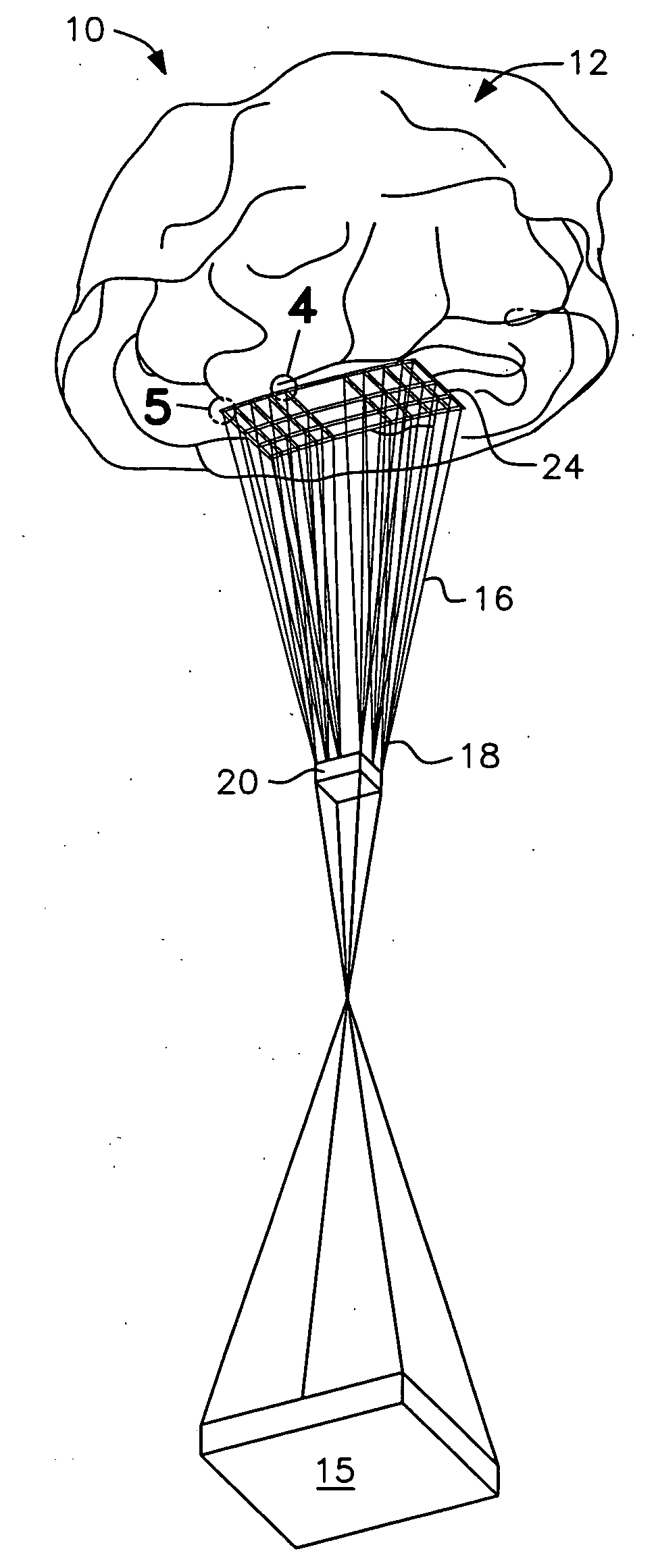
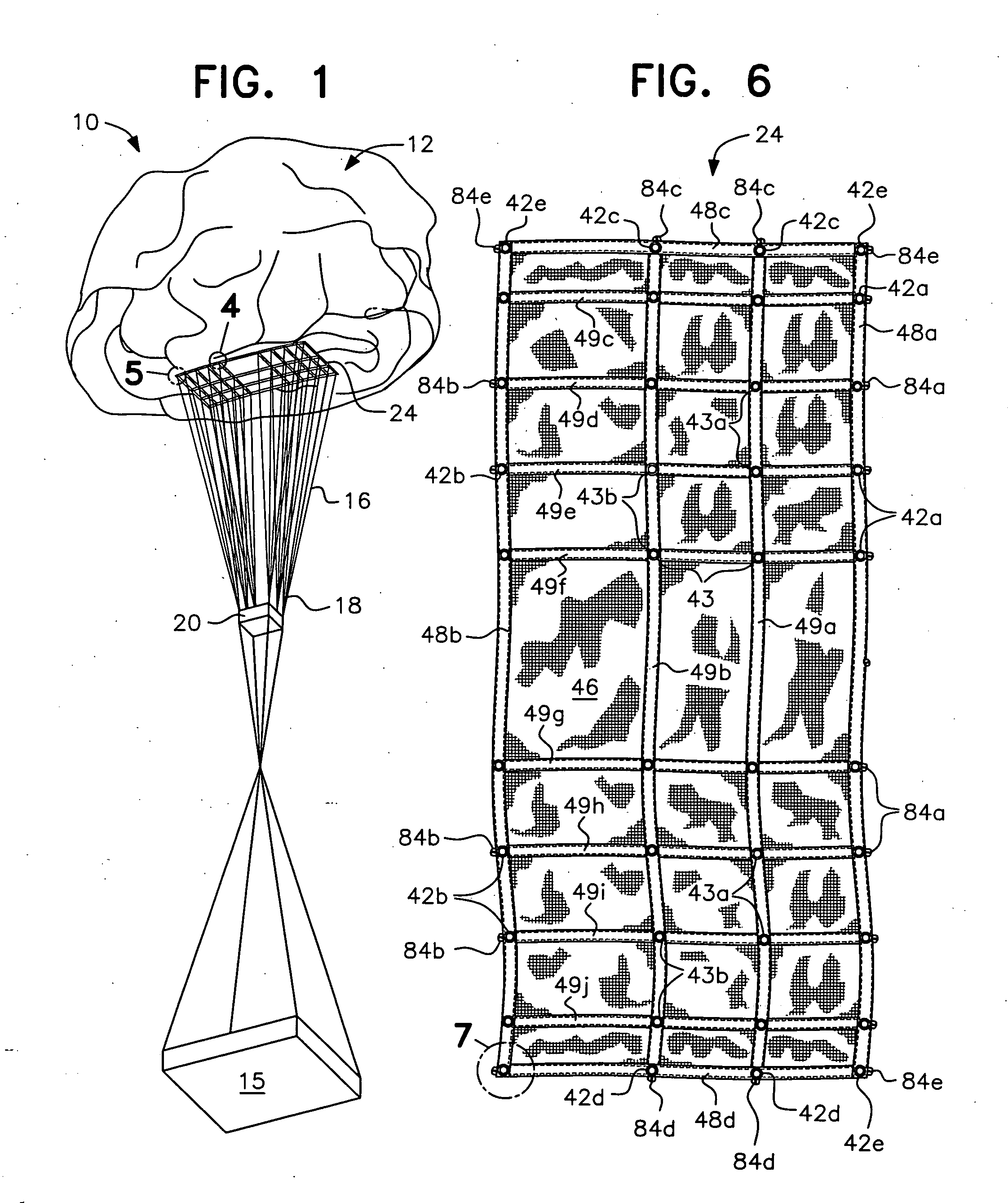
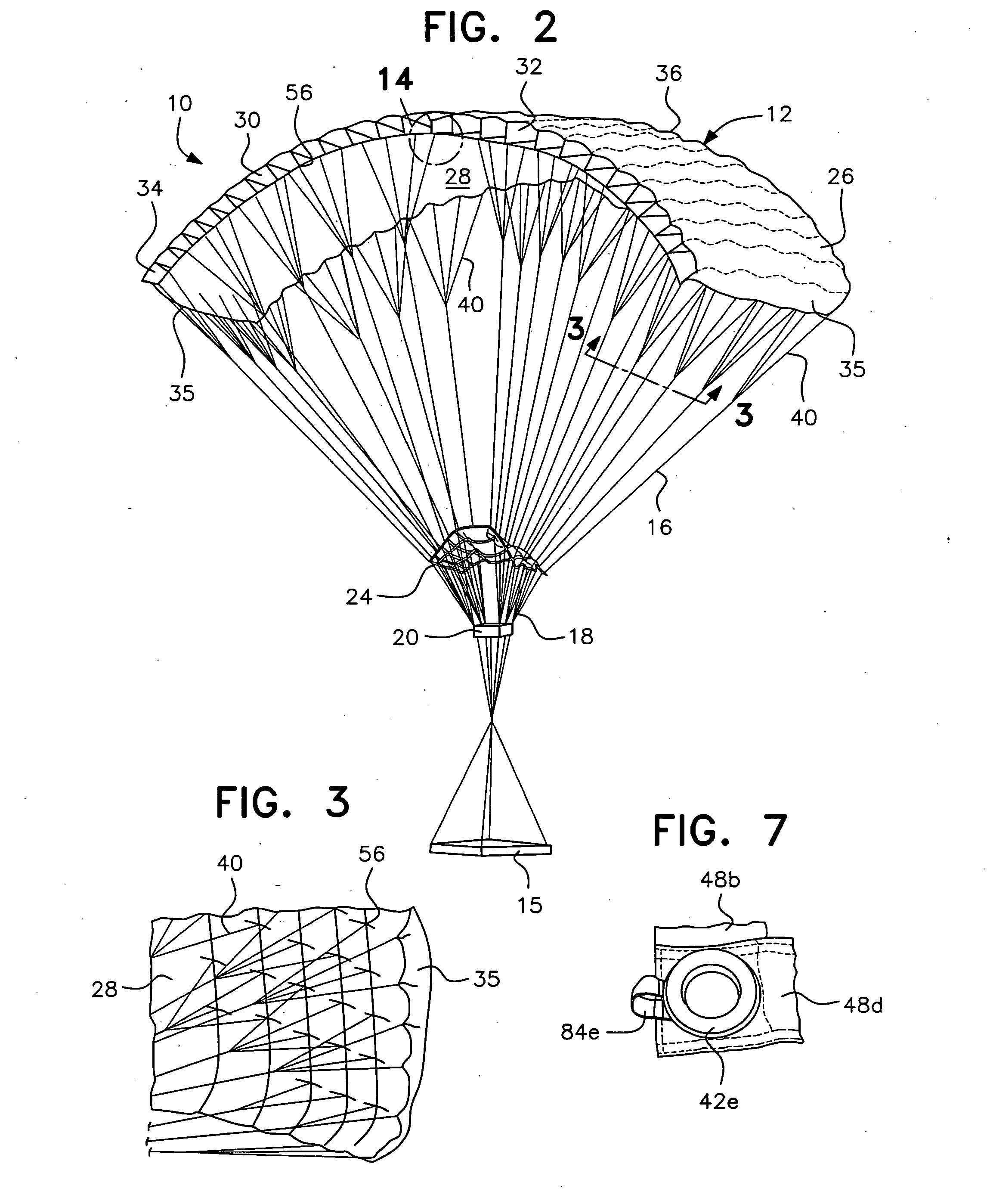
[0040]Referring now to the drawings in detail, FIGS. 1 and 2 illustrate a ram air parachute, generally designated by the reference numeral 10, in a partially deployed and a fully deployed condition, respectively. The parachute includes a canopy generally designated by the reference numeral 12, shown fully inflated in FIG. 2, from which a payload 15 is suspended by means of a plurality of suspension lines 16 connected at their upper ends to the bottom surface of the canopy at suspension line attachment points 56, as shown in FIG. 3. Groups of adjacent suspension lines 16 are anchored at their low...


PUM


Abstract

A reefing slider for providing improved line management and canopy deployment characteristics of a ram air inflated airfoil type canopy. During initial descent of the parachute the slider, secured by retaining elements, is held against the canopy in the upper reefing position where it mechanically restricts canopy deployment while giving the canopy time to achieve proper orientation following the drop from the launching aircraft. Upon sufficient air flow into the canopy cells, the retaining elements separate, releasing the slider and enabling full opening of the canopy.

Description

RELATED APPLICATIONS[0001]This application is a continuation-in-part of copending application Ser. No. 11 / 201,186, filed Aug. 11, 2005, issuing as U.S. Pat. No. 7,338,016 on Mar. 4, 2008, and hereby claims the priority thereof to which it is entitled.BACKGROUND OF THE INVENTION[0002]1. Field of the Invention[0003]The present invention relates in general to delaying the opening of parachute canopies and, more particularly, to a slider type reefing device that is secured to the canopy during initial parachute deployment.[0004]2. Description of the Related Art[0005]A known problem with the use of parachutes to lower personnel and unmanned cargo to the ground from airplanes and other airborne craft is the sudden shock when the parachute opens and fills quickly with air. This is especially serious at high speeds where the canopy fills more rapidly, as may occur during the deployment of parafoils designed to fly at high wing loadings.[0006]The mechanical reefing of parachute canopies by s...

Claims


Application Information

Patent Timeline
Patent Type & Authority Applications(United States)
IPC IPC(8): B64D17/00
CPCB64D17/025B64D17/343B64D17/26
Inventor BERLAND, JEAN C.
Owner AIRBORN SYST NORTH AMERICA OF NJ INC
Learn More